Uponor c56 Installation And Operation Manual Download Page 40

Set automatic daylight saving

For European zone CET, an automatic time adjustment is made 
complying with European directive 2000/84/EC.

For countries in the southern hemisphere, set the end date 
earlier than the start date.

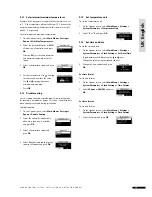
To set automatic daylight saving:

1  On the Uponor screen, select 

Main Menu > Settings > 

System Parameters > Clock Settings > Auto Daylight 
Saving

2  Select the desired setting and press 

OK

3  Fixed date allows manual setting of 

the dates.

 Enter 

Start

 date and 

End 

date of 

summer time and press 

OK

9.16  Use ECO mode

Use ECO to save energy. In heating mode, ECO mode reduces 
room temperatures at the set times. In cooling mode, it 
increases the temperature. Different ECO profi les may be 
applied to a thermostat for each day of the week.

The ECO profi le provides fi ve different time/temperature 
profi les. The names indicate their specifi c application. All 
profi les can be modifi ed. In the event of a power failure, all 
customised settings are saved.

Cooling ECO profi les are displayed only when cooling is 
activated and set in the system parameters menu.

ECO mode setting

Description

ECO Off

ECO All

ECO mode active:
From 9.30 a.m. to 2.30 p.m.

ECO Night & Day

For example, ECO mode active:
From 10.30 p.m. to 5.00 a.m.
From 9.30 a.m. to 2.30 p.m.

ECO Custom

For example, ECO mode active: 
From 00.30 a.m. to 5.30 a.m.
From 12.00 a.m. to 5.30 p.m.

ECO Night

For example, ECO mode active: 
From 10.30 p.m. to 5.00 a.m.

The Uponor Remote access module R-56 allows switching 
between Comfort mode and ECO mode, by using a mobile 
telephone.

Edit ECO profi les

After making modifi cations, profi les cannot be reset to their 
initial values, except by modifying them again. 

Modify the profi les fi rst, then defi ne the thermostats that each 
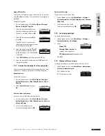
profi le controls. To edit ECO profi les:

1  On the Uponor screen, select 

Main Menu > Settings > 

Edit ECO Profi les

2  Select the ECO profi le to modify and 

press 

OK

 Modify 

ECO


profi le, then confi rm by 

pressing 

OK

3  To modify the profi le, select the time using the   and    

keys to move in increments of 30 minutes. The set time is 
indicated above the time profi le.

 Apply 

Comfort

 mode by pressing the 

 key.

 Apply 

ECO

 mode by pressing the 

 key. 

4  To set a complete period with the same mode: 


•  Move the cursor to the start time of the period. 


•  Set the start time: by briefl y pressing the 

 or 

 key.


•  Move the cursor to the end time of the period.


•  Press and hold the 

 or 

 key.

 The 

profi le applies from start time to end time. 

5  Modify the correction value of the 

temperature set point for the ECO 
mode and press 

OK

4 0

U P O N O R   C O N T R O L   S Y S T E M   –   I N S TA L L AT I O N   A N D   O P E R AT I O N   M A N U A L

UK  English

Summary of Contents for c56

Page 1: ...01 2009 IND OOR CLIMATE UPONOR CONTROL SYSTEM Uponor Control System Installation and Operation Manual...

Page 2: ...Interface I 76 only 28 Optional auto balance Interface I 76 only 28 Room check Interface I 76 only 28 Supply diagnostics Interface I 76 only 29 Optional comfort setting Interface I 76 only 29 6 Troubl...

Page 3: ...J 9 connector on Interface I 75 76 Using the 15 m four wire connector cable or similar Connect terminals 1 2 3 and 4 on the controller to terminals 1 2 3 and 4 on the Uponor Interface I 75 76 Wiring i...

Page 4: ...peration for controller 2 the controller connected to terminals 5 and 6 and controller 3 the controller connected to terminals 7 and 8 10 Press OK to end identi cation Register thermostats 1 Press the...

Page 5: ...come on 2 Press and hold the button of the chosen channel until the channel LED goes off The thermostat is now unregistered 3 Press and release the Test button to exit The test LED goes off Deregiste...

Page 6: ...s 50 Hz 230 V AC power In case of emergency immediately disconnect the power Limitations for radio transmission The Uponor Control System uses radio transmission The frequency used is reserved for sim...

Page 7: ...products approved or speci ed by Uponor e is not connected to or used with non Uponor products parts or components except for those approved or speci ed by Uponor and f does not show evidence of tampe...

Page 8: ...8 U PONOR CONTROL SYSTEM INSTAL L ATION AND OP ER ATION MANUAL UK English...

Page 9: ...be used with an outdoor sensor 5 Uponor Controller C 55 56 6 Uponor Antenna for controller C 55 56 7 Uponor Interface I 75 76 8 External connection box for pumps third party product just schematic exa...

Page 10: ...thermostat temperature settings are adjusted using the dial which is removed to set minimum maximum temperatures The 21 C position is marked with a larger line The table below describes the components...

Page 11: ...kit Uponor Interface I 75 76 can be purchased in a kit together with Uponor Controller C 55 56 The table below describes the components of the interface with controller kit The item numbers correspond...

Page 12: ...r 6 Repeater to strengthen signal between thermostat and controller Uponor outdoor sensor 7 Outdoor sensor for use with Uponor Thermostat T 54 Public Uponor Floor sensor 8 Floor sensor for use with Up...

Page 13: ...I 75 76 Follow the process described below to install the Uponor Interface I 75 76 Stage Description Page 1 Attach Interface I 75 76 to bracket 23 2 Wire Interface I 75 76 to Controller C 55 56 23 3 O...

Page 14: ...efore installing the Uponor Control System Check the contents of the packages against the packing list to ensure that all components are present Check if an external sensor is to be installed with Upo...

Page 15: ...antenna can be attached to the back of the controller or to the wall If the controller is installed inside a metal cabinet the entire antenna must be outside the cabinet as shown in the illustration b...

Page 16: ...el it must be connected to 3 4 Optional connect heating cooling input If the system is equipped with a cooling unit requires additional products the Uponor Control System can manage the heating coolin...

Page 17: ...to the controller To connect circulation pump management 1 Ensure the power is disconnected 2 Open the 230 V compartment and attach the cover to the hanger 3 Connect the L wire from to the pump via t...

Page 18: ...ted channel The LED comes on which means that the controller receives a signal and powers the actuator on the selected channel The time for actuator opening is about 5 minutes If the LED does not come...

Page 19: ...ic equipment replace Away from direct sunlight Away from water splashes 4 1 Optional connect Thermostat T 54 Public to external sensor Uponor Thermostat T 54 Public has a terminal for connecting an ex...

Page 20: ...have a higher priority than room thermostat Wire external sensor to Thermostat T 54 Public 1 Connect cable from the oor or outdoor sensor non polarized 2 Tighten the screws to x the cable wires For a...

Page 21: ...LED comes on 2 Press and release the button of the chosen channels in the controller The channel LEDs ash 3 Using a pointed instrument gently press the registration button of each thermostat until the...

Page 22: ...d channel LEDs with registered thermostats comes on 2 Using a pointed instrument gently press the registration button of each registered thermostat Communication OK LEDs for the channels registered to...

Page 23: ...ation below shows how to attach a bracket to a wall Attach bracket to controller cover The illustration below shows how to attach the bracket to the cover of the controller 1 3 2 4 1 2 Attach Interfac...

Page 24: ...roller C 55 56 units require software programming Up to three controllers can be connected to the same Uponor Interface I 75 76 All controllers require an antenna as shown in the illustration below In...

Page 25: ...Uponor Interface I 75 76 for the rst time the language menu appears To access the language menu when Interface I 75 76 is installed 1 On the Uponor screen press the OK button to access the Main Menu 2...

Page 26: ...s can be set only when Uponor Interface I 75 76 is set to Installer level access To set controller IDs for Interface I 75 76 1 On the Uponor screen select Main Menu Settings System Parameters Controll...

Page 27: ...ings System Parameters Cooling Available 2 Select Yes and press OK 3 Select Auto heating cooling manages the switchover automatically by an Uponor heating cooling relay connected to a controller Force...

Page 28: ...balancing of the manifold at installation The principle for automatic balancing is that the energy required by each loop is distributed in pulses The length of the pulses in each loop is calculated fr...

Page 29: ...elect Activate and press OK 5 18 Optional comfort setting Interface I 76 only The comfort setting function adds background heating for increased comfort in selected rooms This means that the room is h...

Page 30: ...ow shows the location of the reset button in Uponor Controller C 55 56 To reset Uponor Controller C 55 56 1 Press the Test button until the test LED ashes and all LEDs except the power LED go off All...

Page 31: ...nction can be used at any time Clean controller Use a dry soft cloth to clean Uponor Controller C 55 56 Do not use detergent or any other liquids If no Uponor Interface I 75 76 is connected to the sys...

Page 32: ...rmat to Celsius or Fahrenheit 1 Simultaneously press the and keys until the SEL menu appears 2 Press or to change the temperature format C or F and wait until the thermostat returns to the initial dis...

Page 33: ...r temperature Rotate the dial anti clockwise for a lower temperature Set minimum maximum temperatures The illustration below shows how to set minimum and maximum temperatures in the thermostat If the...

Page 34: ...AUTION Thermostats are located in speci c areas for optimum performance Changing the location of thermostats can cause abnormal temperature control Change temperature set point It is not possible to s...

Page 35: ...ensitive oor covering from exposure to excessive high temperature when there is a high heat demand 20 25 30 35 40 45 Embedded in concrete or slab Embedded in wooden suspended oor To change Uponor Ther...

Page 36: ...e Displays next screen or Con rms selections displays screen of current menu Press any navigation key to activate backlighting Press OK to go to the main menu 9 2 Interface I 75 76 main screen The tab...

Page 37: ...digits at the beginning of the room name on the display mean 1st digit controller number 1 2 3 2nd and 3rd digits number of the rst channel controlled by this thermostat 01 02 03 and so on If several...

Page 38: ...iday mode temperature is set to 15 C for all rooms the temperature for this room will not go below 20 C Floor sensor thermostat settings have priority over holiday mode maximum and minimum limitations...

Page 39: ...ponor screen select Main Menu Settings Rooms Disable Cooling 2 Select the controller applies only when more than one is installed and press OK 3 Select a thermostat or room and press OK 4 Select Yes t...

Page 40: ...mode active From 10 30 p m to 5 00 a m From 9 30 a m to 2 30 p m ECO Custom For example ECO mode active From 00 30 a m to 5 30 a m From 12 00 a m to 5 30 p m ECO Night For example ECO mode active From...

Page 41: ...ponor screen select Main Menu Settings System Parameters Valve Pump Exercise Cancel Exercise 2 Select Cancel Exercise and press OK Exercise valves and pumps To run the exercise for both valves and pum...

Page 42: ...ponor screen select Main Menu Information Alarms Battery Alarm 2 Select the desired alarm and press OK The example screens show a battery alarm for a living room thermostat Change batteries in both ro...

Page 43: ...tration in Controller C 55 56 White indicator cannot be seen in indicator window of actuator Actuator does not open Replace actuator Contact installer Set point temperature displayed in room informati...

Page 44: ...rs are saved Reset Interface I 75 76 11 1 Thermostat with display T 75 alarms problems An alarm is sent when more than 3 hours have elapsed since the controller received the last radio signal from the...

Page 45: ...blems that can occur in the Controller C 55 56 Indication Causes Solutions Power LED and channel LEDs in the Controller C 55 56 ash Antenna out of position or wire disconnected Install antenna in corr...

Page 46: ...ength guaranteed without any EMC problems Gauge wire Cable from controller to antenna 0 30 m 3 m 25 m Controller 0 2 mm to 1 5 mm Antenna Plug connector Cable from controller to interface 2 m 15 m 20...

Page 47: ...wer Two 1 5 V AAA alkaline batteries Voltage 2 2 V to 3 6 V Operating temperature 0 C to 45 C Storage temperature 10 C to 65 C Radio frequency 868 3 MHz Transmitter duty cycle 1 Interface CE marking L...

Page 48: ...Pro les ECO Pro le List Modify Heating Cooling and range Controller List Controller List Controller List Controller List Controller List Room List Room List Room List Room List Room List User Input U...

Page 49: ...time C or F Always ON Dimmed when inactive OFF when inactive Basic Advanced User Input Day of week and time Auto Heating Cooling Forced Heating Forced Cooling Common or Individual Reset Controller ID...

Page 50: ...orage temperature 20 C to 70 C Max consumption 1 W Antenna Power supply 11 V DC 10 from controller Consumption less than 1 W Radio Frequency 868 3 MHz Transmitter duty cycle 1 Receiver class 2 Control...

Page 51: ...nnector 3 Buttons and LEDs from 01 to 12 for channel registration 4 Test button and LED 5 Quick connectors for actuators 6 Data stick connection 7 Power LED 8 50 Hz 230 V AC power compartment and pump...

Page 52: ...Installation report 24 V 24 V 24 V Controller number Channels Rooms 1 Floor sensor Relay Yes 24 V No 230 V Pump Yes No 52 U PONOR CONTROL SYSTEM INSTAL L ATION AND OP ER ATION MANUAL UK English...

Page 53: ...24 V 24 V 24 V Controller number Channels Rooms 2 Floor sensor Pump Yes No 3 Floor sensor Pump Yes No Option 53 UPO N O R CO N T ROL SYST EM I NSTALLAT ION A ND OP ERATION MANUAL UK English...

Page 54: ...54 U PONOR CONTROL SYSTEM INSTAL L ATION AND OP ER ATION MANUAL UK English...

Page 55: ...55 UPO N O R CO N T ROL SYST EM I NSTALLAT ION A ND OP ERATION MANUAL UK English...

Page 56: ...Fax 44 1455 550 366 Leicestershire LE17 4HN www uponorhousingsolutions co uk Uponor reserves the right to change speci cations without prior notice in keeping with our policy of continuous improvement...

Reviews: