


1
2
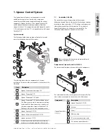
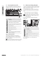
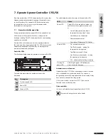
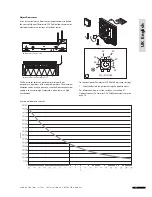
Example installation with fl oor sensors
The example below shows an installation of thermostats in a
room with fl oor sensors. Uponor Thermostat T-54 Public 01 and
10 are connected to fl oor sensors.
In the example, Uponor Thermostat with display T-75 #01
controls channels 01a, 01b, 02a, and 02b. Uponor Thermostat
T-54 Public communicates fl oor temperature to the controller.
Uponor Thermostat with display T-75 #03 controls channels 03
and 04.
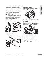
If the external sensor thermostat is registered to a
channel used by a room thermostat, then the room
thermostat must be registered before registering the
external sensor thermostat. Thermostats with fl oor
sensors have a higher priority than room thermostat.
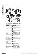
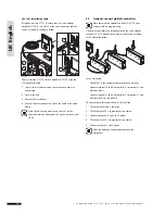
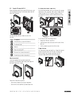
Wire external sensor to Thermostat T-54 Public
1 Connect cable from the fl oor or outdoor sensor (non-
polarized).
2 Tighten the screws to fi x the cable wires
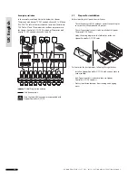
For accurate temperature: attach the outdoor sensor
on the north side of the building where it is unlikely to
be exposed to direct sunlight. Do not place it close to
doors, windows, or air outlets.
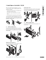
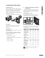
Adjust fl oor sensor settings
The Uponor Thermostat T-54 Public sends the external sensor
values to the controller. Temperature settings can be adjusted by
using the potentiometer, as shown in the illustration below.
To adjust fl oor minimum or maximum temperature:
1 Select the required temperature with the potentiometer.
24 V
24 V
24 V
24 V
24 V
24 V
24 V
24 V
24 V
20
25
30
35
40
45
2 0
U P O N O R C O N T R O L S Y S T E M – I N S TA L L AT I O N A N D O P E R AT I O N M A N U A L
UK English


