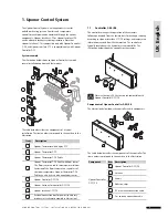


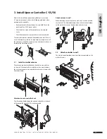


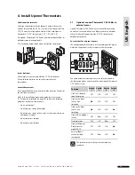


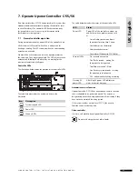


5. Install Uponor Interface I-75/76
Refer to the installation preparation guidelines (section 2.1
Prepare for installation on page 14). Uponor Interface I-75/76
can be attached to a wall or to the cover of the controller.
Additional controllers must be installed for installations with
more than one manifold or more than 12 channels. One Uponor
Interface I-75/76 supports a maximum of three controllers,
where each controller must be equipped with an antenna.
WARNING
50 Hz 230 V AC power.
Disconnect all power before installing or changing the
device wiring.
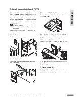
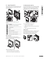
Uponor Interface I-75/76 is attached to a bracket that in turn is
attached to either a wall or the controller cover.
Attach bracket to wall
The illustration below shows how to attach a bracket to a wall.
Attach bracket to controller cover
The illustration below shows how to attach the bracket to the
cover of the controller.
1
3
2
4
1
2
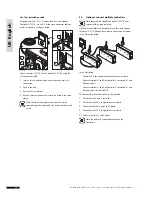
Attach Interface I-75/76 to bracket
The illustration below shows how to attach Uponor Interface
I-75/76 to the bracket.
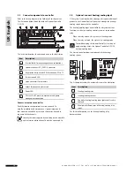
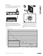
5.1
Wire Interface I-75/76 to Controller C-55/56
Use RJ-9 connectors
If Uponor Interface I-75/76 is less than 2 m from Uponor
Controller C-55/56, then use the 2 m cable equipped with RJ-9
connectors at each end, as shown in the illustration below.
To wire Uponor Interface I-75/76 to Uponor Controller C-55/56
with the RJ-9 cable:
1 Connect the RJ-9 cable to the controller.
2 Secure the cable in the clamp.
3 Connect the RJ-9 cable to the back of Uponor Interface
I-75/76.
4 Secure the cable in the cable guide.
1
2
3
4
3
4
2 3
U P O N O R C O N T R O L S Y S T E M – I N S TA L L AT I O N A N D O P E R AT I O N M A N U A L
UK English


