


MSC-400 Reference Manual
Rev 4
32
a)
Set the PRIMARY and SECONDARY RFIDs. Activate the Secondary RFID (click/check mark in
the box). Use one RFID from ID 11-1F
for IR CONTROL from PORTS 1-6 (Primary),
and a
DIFFERENT RFID from ID 11-1F for IR CONTROL from PORTS 7-12 (Secondary).
NOTE - The Instructions in Steps 4-5 relate to IR Control from Ports 7-12. If only RS232
Devices are controlled via Ports 7-12, then any RFID can be used for any remote and the
Secondary RFID does not need to be set in Step 5.
6.
In the SENSOR PORT SETTING BOX, under SENSOR, click EITHER. From the pull-down, select
the TYPE
of SENSOR being used for the DEVICE connected to that SENSOR INPUT.
TIP - Create a table that shows all devices by type/brand/model, IR/RS232 Port and Sensor
Port to assist in making connections and configuring Sensor inputs and IR/RS232 Ports.
Whenever possible, try to use the same number Sensor Port as IR/RS232 Port for a given
device, to keep things simple when making connections and trouble shooting.
7.
Under DESCRIPTION (Edit Control), double click the line of the DEVICE being cond. The
PORT
INFORMATION SETTING WINDOW will appear.
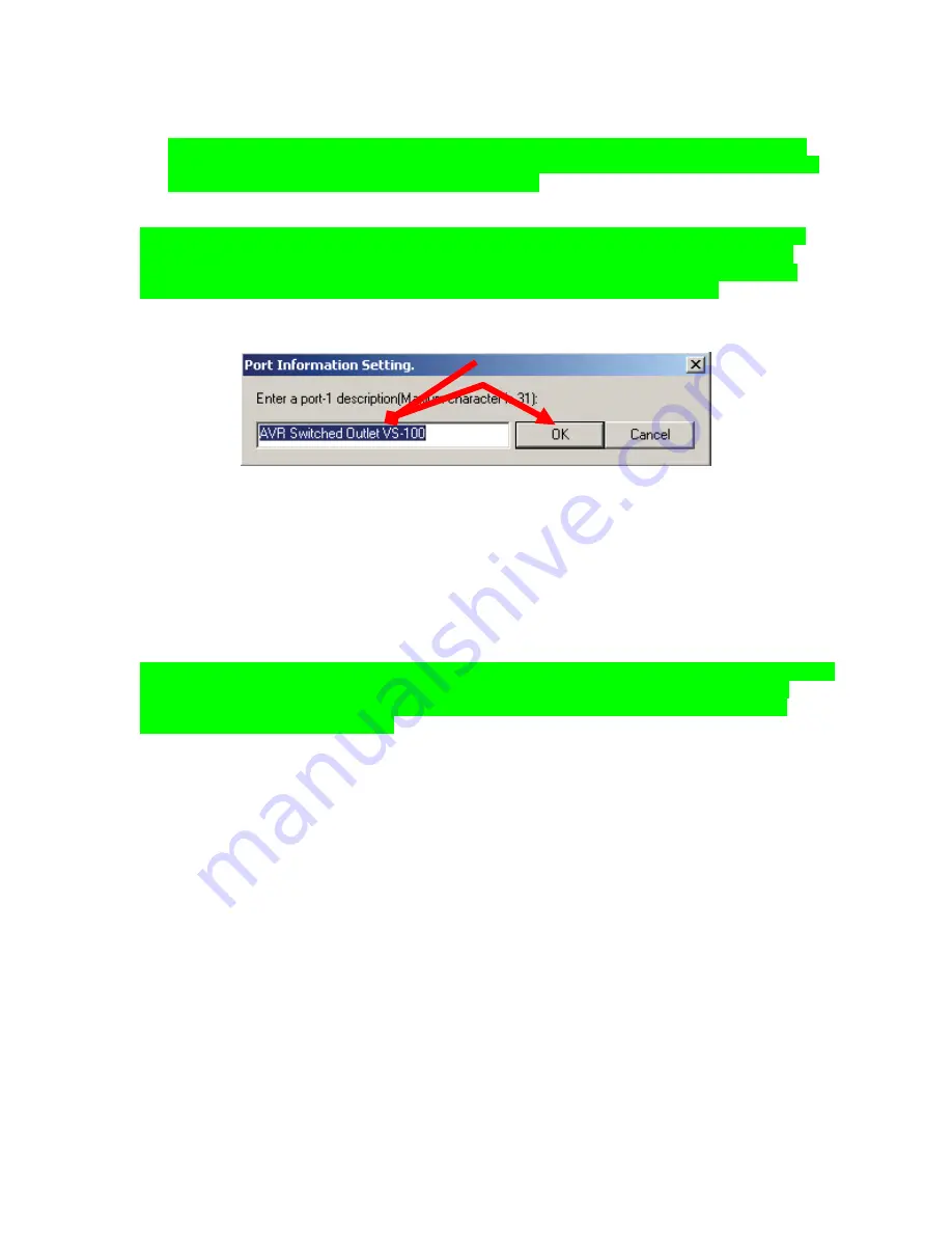
Port Information Setting Window.
Port Information Setting Window
8.
In the PORT INFORMATION SETTING WINDOW, type the name of the DEVICE and a short
description of the SENSING METHOD for that device (31 characters total). Be clear in the description
as this information will become useful when configuring Smart Macros. Click OK to enter the
information and close the window.
9.
In the SERIAL PORT SETTING BOX, click the PORT to be cond. The entire line will highlight and
PULL-DOWNS will appear for all RS232 PROTOCOL PARAMETERS. Use the pull-downs to con
EACH SETTING to the appropriate value.
NOTE - The Serial Port values must be set to the proper factory settings for each device being
controlled via RS232. Refer to the owner’s manual or manufacturer’s web site for RS232
settings and commands. It may be necessary to contact some manufacturers’ technical
support to obtain this information.
10.
Under DESCRIPTION (Edit Control), on the line of the SERIAL PORT being cond, double click the
blue highlight. The PORT INFORMATION SETTING WINDOW will appear. Type the name of the
DEVICE being controlled via that port and any important CONTROL INFORMATION that is worth
noting. Click OK to enter the information and close the window.
11.
When ALL FIELDS in CONFIGURATION have been set, click OK to save settings.
At this point, the fundamental elements of MSC-400 configuration are in place. The Connected Devices
and their commands have been imported, the IR and RS232 Ports have been assigned and the Voltage
and Video Sensors cond. These are the basic building blocks of MSC-400 system control. The following
sections will take those building blocks and use them in various ways to control everything from individual
device functions to System ON/OFF Macros, Source Select Macros and conditional IF/ELSE Smart
Macros that look at various elements of system and device status to determine which commands to send
when, for an endless potential of system modes that meet any user requirements.
8
Summary of Contents for MSC-400
Page 1: ...MSC 400 Reference Manual ...
Page 3: ...MSC 400 Reference Manual Rev 4 3 MSC 400 Reference Manual Section One Features and Parts ...
Page 12: ...MSC 400 Reference Manual Rev 4 12 MSC 400 Reference Manual Section Two Installation ...
Page 21: ...MSC 400 Reference Manual Rev 4 21 MSC 400 Reference Manual Section Three Programming ...
Page 57: ...MSC 400 Reference Manual Rev 4 57 5 Click OK The MSC 400 is ready for action 5 ...
Page 83: ...MSC 400 Reference Manual Rev 4 83 MSC 400 Reference Manual Section Seven Master Slave Systems ...
Page 91: ...MSC 400 Reference Manual Rev 4 91 MSC 400 Reference Manual Section Eight Troubleshooting ...


