


2.5. Tool I/O
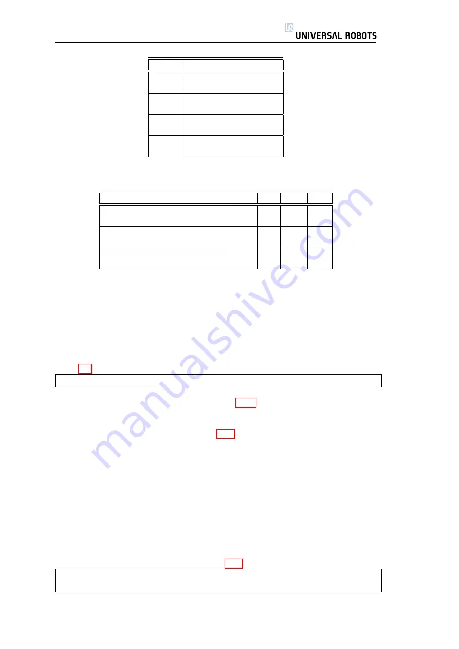
Colour
Signal
Red
0V (GND)
Gray
0V/12V/24V (POWER)
Blue
Digital output 8 (DO8)
Pink
Digital output 9 (DO9)
Yellow
Digital input 8 (DI8)
Green
Digital input 9 (DI9)
White
Analog input 2 (AI2)
Brown
Analog input 3 (AI3)
Table 2.9: Relation between cable colours and functions.
Parameter
Min
Typ
Max
Unit
Supply voltage in 24V mode
TBD
24
TBD
V
Supply voltage in 12V mode
TBD
12
TBD
V
Supply current in both modes
-
-
600
mA
Short-circuit current protection
-
650
-
mA
Capacitive load
-
-
TBD
uF
Inductive load
-
-
TBD
uH
Table 2.10: Data specification of tool power supply. TBD = To Be Determined.
This connector provides power and control signals for basic grippers and sen-
sors, which may be present at on specific robot tool. The reason for having this
connector is to save the wiring between the tool and the controller box. It is of
course necessary to add wires if the I/O provided is insufficient. The connector is
a standard Lumberg RSMEDG8, which mates with a cable named RKMV 8-354.
Table 2.9 shows the different I/O and the corresponding cable colors.
Note that the tool flange is connected to GND (same as the red wire).
The available power supply can be set to either 0V, 12V or 24V at the I/O tab
in the graphical user interface (see section 3.3.2). Take care when using 12V,
since an error made by the programmer can cause a voltage change to 24V,
which might damage the equipment and even cause a fire. The specifications
on the power supply are shown in Table 2.10.
The internal control system will generate an error to the robot log if the current
exceeds its limit. The different I/Os at the tool is described in the following three
subsections.
2.5.1
Digital Outputs
The digital outputs are implemented so that they can only sink to GND (0V) and
not source current. When a digital output is activated, the corresponding con-
nection is driven to GND, and when it is deactivated, the corresponding con-
nection is open (open-collector/open-drain). The primary difference between
the digital outputs inside the controller box and those in the tool is the reduced
current due to the small connector. Table 2.11 lists the specified data.
Note that the digital outputs in the tool are not current limited and overriding
the specified data can cause permanent damage.
To illustrate clearly how easy it is to use digital outputs, a simple example is
shown.
29
UR-6-85-5-A
Summary of Contents for UR-6-85-5-A
Page 1: ...UR 6 85 5 A User Manual Version 1 11 January 2010...
Page 2: ...2 UR 6 85 5 A...
Page 6: ...Contents 6 UR 6 85 5 A...
Page 16: ...1 4 Mounting Instructions 16 UR 6 85 5 A...
Page 33: ...Chapter 3 PolyScope Software 33...


