


2.2. The Emergency Stop Interface
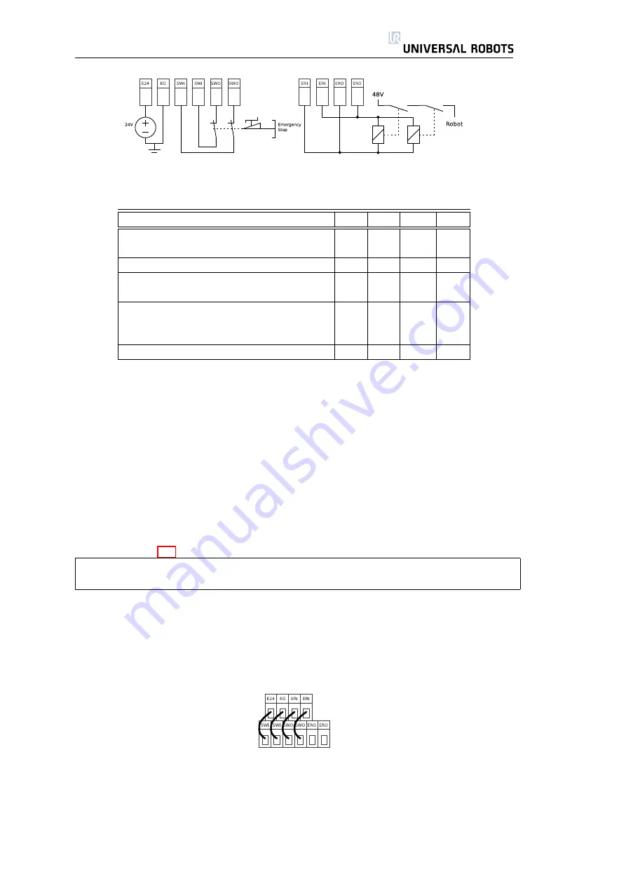
Figure 2.1: Simplified schematics of the internal robot emergency stop circuitry.
Parameter
Min
Typ
Max
Unit
Voltage available at connection E24
TBD
24
TBD
V
Current available at connection E24
-
-
800*
mA
Short-circuit current protection
-
850
-
mA
Capacitive load at connection E24
-
-
TBD
uF
Inductive load at connection E24
-
-
TBD
uH
Emergency relay ON voltage
18
24
26
V
Emergency relay OFF voltage
-
0
1.5
V
Emergency relay quiescent current
-
110
TBD
mA
Current through internal switch
-
-
1.0
A
Table 2.2: Emergency stop interface data. TBD = To Be Determined.
as long as only one error appears at a time. Failure and abnormal behavior
of relays and power supplies results in an error message in the robot log and
prevents the robot from powering up.
It is generally important that the connections to the emergency stop inter-
face are separated from the normal I/O interface, and that it is never con-
nected to a PLC which is not a safety PLC with the right safety level. If this rule
is not followed, it is not possible to get a high safety level, because one failure
in normal I/O can prevent an emergency stop signal from resulting in an emer-
gency stop. Other rules that restrict the use of the emergency stop interface are
shown in table 2.2.
Note that connection E24 is sourced by the same internal 24V regulator as the
normal I/O, and that the maximum of 800mA is for both power sources together.
The internal control system will power off the robot if the current exceeds its
limit. This will also generate an error message in the robot log. The next subsec-
tions show some simple examples of how the emergency stop interface can be
connected to other safety equipment and other safety circuits.
2.2.1
The Simplest Emergency Stop Configuration
The simplest configuration is to use the internal emergency stop button as
the only component to generate an emergency stop. This is done with the
configuration shown above. This configuration is the default when the robot
leaves the factory, and thereby the robot is ready to operate. However, the
emergency configuration should be changed if required by the risk assessment.
19
UR-6-85-5-A
Summary of Contents for UR-6-85-5-A
Page 1: ...UR 6 85 5 A User Manual Version 1 11 January 2010...
Page 2: ...2 UR 6 85 5 A...
Page 6: ...Contents 6 UR 6 85 5 A...
Page 16: ...1 4 Mounting Instructions 16 UR 6 85 5 A...
Page 33: ...Chapter 3 PolyScope Software 33...


