CHAPTER 4: USER MAINTENANCE
9100 SERIES REFLOW SOLDERING SYSTEM
990-606
4-3
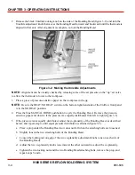
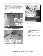
3 Remove the hose connected between the vacuum
generator and the hub fitting by carefully pulling the
hose, with a twisting motion, from the generator, and
then unscrewing the other end from the hub
(figure 4-4).
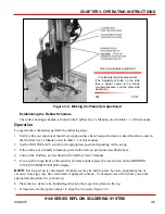
4 Remove twelve cap screws that secure the rotary table
to the workstation (figure 4-5).
Figure 4-4. Removing Vacuum
Generator Hose to the Hub
PULL OUT HOSE TO
VACUUM GENERATOR
UNSCREW FITTING
FROM HUB
REMOVE 12
CAP SCREWS
CAUTION
EITHER PROP UP OR RETRACT
BONDING HEAD TO PREVENT
DAMAGE FROM ROTARY TABLE
CAUTION
DO NOT BANG PROXIMITY
SENSOR
WHEN REMOVING
ROTARY TABLE
Figure 4-5. Removing Rotary Table
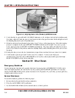
APPLY LIGHT
GREASE TO
GEAR TEETH
APPLY LIQUID
LUBRICANT TO
LUBRICATORS
(2 PLACES)
Figure 4-6. Lubricating Gears and Lubricators
CAUTION:
When removing the rotary
table, be careful not to hit the proximity
sensor or bonding head.
5 Carefully pull up on the rotary table
to remove it.
6 Apply a light grease to the gears
and oil to the lubricators.
7 Return the rotary table by reversing
the above steps.
Summary of Contents for 9100 Series
Page 14: ......
Page 25: ...9100 SERIES REFLOW SOLDERING SYSTEM 990 606 A 1 APPENDIX A SPECIFICATIONS...
Page 32: ......

