CHAPTER 1: SYSTEM DESCRIPTION
9100 SERIES REFLOW SOLDERING SYSTEM
990-606
1-5
10
TABLE INDEX
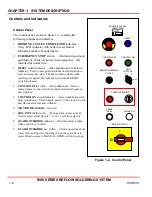
switch - (White pushbutton) Used in conjunction with the left hand READY TO INDEX
switch (see workstation controls) to index the table without activating the bonding head. Is useful for
removing the last unit from the workstation at the completion of a job.
11
MAINS ON
indicator - (White indicator) Lights to indicate that the MAIN ISOLATOR switch is on and
power is applied to the workstation.
12
MAIN ISOLATOR
switch - (Red rotary switch) Used to apply main power to the workstation (1). The (0)
position removes the power.
Tabletop Controls
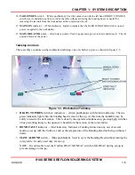
There are three controls on the workstation tabletop, one of which is a pair, as shown in figure 1-3.
Figure 1-3. Workstation Tabletop
1
READY TO INDEX
switches/ indicators - (Green pushbuttons with built-in indicators) The two
green indicators light when the bonding head is clear of the jig. At this time the turntable may be
safely rotated to the next station. This is done by the operator simultaneously pressing both switches
(thus preventing injury to the operator’s hands from the motion of the rotary table).
2
BOND FAULT
indicator - (Red indicator) Indicates a bonding failure due any one of several
faults, as set up with the Uniflow, such as the temperature of the Bonding Head not being within set
limits
3
MANUAL BOND
switch - (Blue pushbutton) Used to cycle the Bonding Head without turning the
rotary table. Usually used only for set-up.
NOTE: It is advisable to set the Uniflow HEAT/NO HEAT switch to NO HEAT during set-up to
prevent damage to the jig.
Summary of Contents for 9100 Series
Page 14: ......
Page 25: ...9100 SERIES REFLOW SOLDERING SYSTEM 990 606 A 1 APPENDIX A SPECIFICATIONS...
Page 32: ......


