23
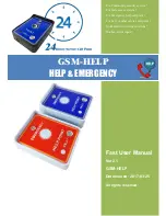
The Emergency Caller
Personal Emergency Response System
Power source:
9-18VDC
Current (OPERATE mode – standby):
28mA typical.
Current (OPERATE mode – dialing):
100mA max.
Activation: Wireless:
1) Activation of the pendant will activate the dialer
2) Aux. Input: Dialer activates when a “close” is detected
(Within the typical home environment)
Max. digits for outgoing numbers:
28
Operating temperature range:
-18 to 55 C (0 to 130 F)
Dimensions (inches):
6 x 4 x 1.5 in
Weight (ounces):
10 oz
Mounting:
Wall or Flat Surface
Case Material:
ABS
Color:
White
Warranty:
1 Year
Note:
Design and specifications subject to change without notice.
Dialer Accessories
S p e c i f i c a t i o n s
Power Source
AC-1P: AC/DC Adaptor
Plugs into regular 110VAC outlet to provide the
dialer with the required primary power.
AC-2: AC/DC Adaptor
12VDC/0.5A for stand alone with siren use.
PP-1: Power (Rechargeable)
Provides 24 (est.) hours of backup standby power.
AC-1: AC/DC Adaptor for Use with PP-1
Plugs into regular 110VAC outlet to provide the
dialer with the required primary power and
additional input for PP-1 interface.
IR-1: Isolation Relay
Converts alarm output voltage to N.C. to provide
clean input trigger to dialer.
Siren
S-120: 2” Mini Siren, 12VDC @ 120 mA typical
Sensors
Magnetic Contacts – Door and Window
Glass Break Detectors
Hold Up Buttons/Emergency Switches
Pressure Mats – Sealed and Under Carpet
Motion Detectors
Industrial/Residential Sensors
F20: Temperature Supervisory Switch <40 F
HTS: High Temperature Switch
LTS: Low Temperature Switch
CSS: Cold Storage Switch
WLS: Water Level Sensor
RTS: Adjustable Temperature Controller, N.O.,
N.C.
PLS: Power Loss Sensor (110VAC)
NOTE:
CALL UNITED SECURITY PRODUCTS
FOR ADDITIONAL INFORMATION AND
DEVICES NOT LISTED HERE.