background image


10


Description 

The Pull-For-Help Transmitter is a digitally coded miniature radio transmitter. The Pull-For-Help Transmitter is 
powered by two long life, selp-contained 3-volt batteries. The transmitter is water-resistant 

but not

 waterproof. 

Do not immerse in water. 
 

Checkout And Test 

Move at least six feet away from 

The Emergency Caller

 and activate the Pull-For-Help Transmitter by pulling 

down on the cord attached to the bottom of the case. 

Emergency Caller

 activation indicates that the Pull-For-

Help Transmitter is operating properly and that the Pull-For-Help Transmitter’s digital code is correctly matched 
to 

The Emergency Caller

. To stop testing simply return the transmitter to its original closed position. 

Operate 

the Pull-For-Help Transmitter from various locations within the area to be used. This will help to locate 
areas where obstacles may interfere with transmission and will identify the range on the transmitter. 


Changing The Batteries 

To replace the batteries in your Pull-For-Help Transmitter you need 2, 3-volt Lithium batteries (Duracell #2025 
or equivalent). 

First be sure to disconnect the dialer from the telephone line. 

Carefully remove the screws on 

the transmitter case.  Remove the clip from the transmitter case and separate the transmitter housing. Carefully 
remove the circuit board inside, and avoid touching any of the components. Remove the old batteries from the 
battery clip, and place the new batteries under the clip  with the positive ends of both batteries facing up. Place 
the circuit board back in the transmitter housing, and reassemble the transmitter case. 

After changing the 

batteries be sure to reconnect the phone line and test the Pull-For-Help Transmitter to make sure you 
have installed the batteres properly.


T h e   P u l l - F o r - H e l p   T r a n s m i t t e r 


CAUTION:


We strongly recommend that you test your cordless Pull-
For-Help Transmitter with 

The Emergency Caller


frequently. From the time of installation, it is absolutely 
necessary to test the system at least once a week to ensure 
that 

The Emergency Caller

 will be ready when needed. 

The batteries should be replaced every year. 

Summary of Contents for 10-4

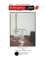
Page 1: ...OWNER S MANUAL AND OPERATING INSTRUCTIONS UNITED SECURITY PRODUCTS INC Emergency Caller HELP GETS FAST The PULL FOR HELP Model 10 4 Automated Call for Help System...
Page 2: ...ed to provide reasonable protection against such interference in a residential installation User Instructions If this equipment does cause interference to radio or television reception which can be de...

Page 3: ...areas exist and where they are located Holding the transmitter next to your body or the ground while in use may decrease the range of the transmitter signal Using The Emergency Caller does not guarant...

Page 4: ...e Pulse dialing Standard telephone line PBX system and Momentary Continuous activation Special Features The dialer will beep every 30 seconds in the Program and Test mode This is to warn the user that...

Page 5: ...tion for single residents latch key children elderly people illness sufferers and others who desire the reassurance of 24 hour peace of mind Combined with the cordless Pull For Help Transmitter The Em...

Page 6: ...ing items 1 Emergency Caller Main unit 2 Long telephone line cord 3 Pull For Help Cordless Transmitter 4 9 12V AC DC adaptor with 3 5mm plug 5 Antenna 6 Pull For Help Transmitter Necklace with Stopper...

Page 7: ...nder normal use transmitter batteries should last 12 18 months Transmitter batteries should be replaced at least once a year To ensure continuous operation during power outages hookup to a 12VDC backu...

Page 8: ...8 P a n e l D i s p l a y s...

Page 9: ...9 OPTIONAL OPTIONAL OPTIONAL I n s t a l l a t i o n H o o k u p...

Page 10: ...ace the batteries in your Pull For Help Transmitter you need 2 3 volt Lithium batteries Duracell 2025 or equivalent First be sure to disconnect the dialer from the telephone line Carefully remove the...

Page 11: ...Necklace Bead To make sure the necklace will not fall off during everyday activities or in case of an accident slide the necklace bead toward your head until t he loop around your neck will not easil...

Page 12: ...S Press these keys to enter telephone numbers and other programming information as specified in this manual A maximum of 28 digits can be input in each phone pager location CALLOUT FOR P Press this ke...

Page 13: ...e number step 3B cellular phone numer step 3B or a voice pager step 3C STEP 3A NUMERIC PAGERS NOTE WHEN PROGRAMMING NUMERIC PAGERS YOU MUST PROGRAM IN ONE OR MORE PAUSES EACH P PROVIDES A 2 SECOND PAU...

Page 14: ...TEP 3C VOICE PAGERS If you pressed 2 and wish to program in a voice pager Press the digits of the pager to be called Press P one or more times in accordance with the number of seconds needed to accomm...

Page 15: ...gramming your dialer to call the police fire department or 9 1 1 directly you must check with these agencies for their approval STEP 1 Before programming write down all your message Time the message c...

Page 16: ...t the option then begin again from Step 3 above to record your new message Programming The Input The Emergency Caller is designed to be adaptable to a complete range of personalized applications The i...

Page 17: ...the operation of your entire system set Mode to OPERATE and proceed as explained in the next section Operating Your System NOTE IN ORDER TO TEST IN THE OPERATE MODE AT LEAST 1 PHONE NUMBER AND OGM OR...

Page 18: ...re the OGM will not be heard through your dialer s speaker but only by each party called To begin operating your system simply press the M Mode key until the word OPERATE appears on the LCD To disarm...

Page 19: ...e you cannot go back to Listen In Remote Turn Off The called party can remotely terminate the activated channel any time during the OGM by pressing 1 then twice within one second The dialer will conti...

Page 20: ...hen press in sequence 3456789PP4455 followed by the sign The first seven digits represent the pager number dialed each P stands for a 2 second pause the next four digits followed by the sign represent...

Page 21: ...lanner in pencil initially After thoroughly testing your system redo your Program Planner in ink One copy should be kept in a safe place by the end user one copy should be retained by the installer P...

Page 22: ...7 ___________ Week 34 ___________ Week 8 ___________ Week 35 ___________ Week 9 ___________ Week 36 ___________ Week 10 ___________ Week 37 ___________ Week 11 ___________ Week 38 ___________ Week 12...

Page 23: ...ired primary power AC 2 AC DC Adaptor 12VDC 0 5A for stand alone with siren use PP 1 Power Rechargeable Provides 24 est hours of backup standby power AC 1 AC DC Adaptor for Use with PP 1 Plugs into re...

Page 24: ...24 United Security Products Inc 1999 Emergency Caller HELP GETS FAST Model 10 4 Automated Call for Help System z 10 6 99 Rev C...

Reviews: