background image

035-14511-000 REV B (1299)

Unitary Products Group

6

® 

The outdoor units have re-usable service valves on both the
liquid and vapor connections. The total system refrigerant
charge is retained within the outdoor unit during shipping and
installation. The re-usable service valves are provided to
evacuate and charge per this instruction.

Serious service problems can be avoided by taking adequate
precautions to assure an internally clean and dry system.

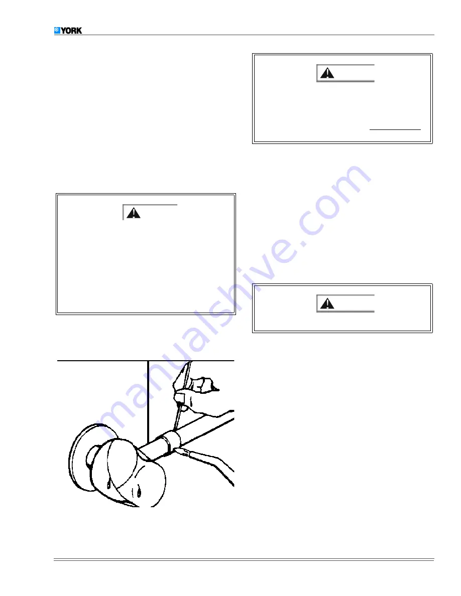
PRECAUTIONS DURING BRAZING ANGLE VALVE

Precautions should be taken to prevent heat damage to
angle valve by wrapping a wet rag around it as shown in Fig-
ure 5. Also, protect all painted surfaces and insulation during
brazing. After brazing - cool joint with wet rag.

Valve can be opened by removing the plunger cap and fully
inserting a hex wrench into the stem and backing out counter-
clockwise until valve stem just touches retaining ring.

Replace plunger cap finger tight, then tighten an additional 1/
12 turn (1/2 hex flat). Cap must be replaced to prevent leaks.

Connect the refrigerant lines using the following procedure:

1.

Remove the cap and Schrader core from both the liquid
and vapor angle valve service ports at the outdoor unit.
Connect low pressure nitrogen to the liquid line service
port.

2.

Braze the liquid line to the liquid valve at the outdoor
unit. Be sure to wrap the valve body with a wet rag. Allow
the nitrogen to continue flowing.

3.

Carefully remove the rubber plugs from the evaporator
liquid and vapor connections.

4.

Braze the liquid line to the evaporator liquid connection.
The nitrogen should now be flowing through the evaporator
coil.

5.

Slide the grommet away from the vapor connection at
the coil. Braze the vapor line to the evaporator vapor
connection. After the connection has cooled, slide the
grommet back into original position.

6.

Protect the vapor valve with a wet rag and braze the
vapor line connection. The nitrogen flow should be exit-
ing the system from the vapor service port connection.
After this connection has cooled, remove the nitrogen
source from the liquid fitting service port.

7.

Evacuate the vapor line, evaporator and the liquid line, to
500 microns or less.

8.

Leak test all refrigerant piping connections including the
service port flare caps to be sure they are leak tight. DO
NOT OVERTIGHTEN (between 40 and 60 inch - lbs.
maximum).

NOTE: Do not use the system refrigerant in the outdoor unit to

purge or leak test.

This is not a backseating valve. The service access
port has a valve core. Opening or closing valve does
not close service access port.

If the valve stem is backed out past the retaining ring,

the O-ring can be damaged causing leakage or sys-
tem pressure could force the valve stem out of the
valve body possibly causing personal injury. In the
event the retaining ring is missing, do not attempt to
open the valve.

FIGURE 5 :

HEAT PROTECTION

WARNI

If visual verification of the valve stem reaching the

retaining ring is impossible, stop backing out the.valve
stem when the slightest increase in resistance is felt.
Because of the small size and therefore the reduced
resistance, back out the liquid valve 
5 turns maximum
to prevent going past the retaining ring.

The evaporator is pressurized.

CAUTIO

CAUTIO

Summary of Contents for H4TS024

Page 1: ...WIRING 8 THERMOSTAT MOUNTING WIRING 8 DE HUMIDIFICATION CONTROL 8 CONTROL WIRING 8 WIRING DIAGRAMS 9 10 INDOOR BLOWER SPEED SETTINGS 8 SYSTEM START UP 11 ENERGIZE CRANKCASE HEATER 11 CHECKING SYSTEM...

Page 2: ...erly INSPECTION As soon as a unit is received it should be inspected for possi ble damage during transit If damage is evident the extent of the damage should be noted on the carrier s freight bill A s...

Page 3: ...jectionable if the unit is placed directly under windows of certain rooms bed rooms study etc ROOF INSTALLATION When installing units on a roof the structure must be capable of supporting the total we...

Page 4: ...7 Install TXV equalizer line in 1 8 hole previously made in vapor line Equalizer line can be bottomed out in vapor line as end of equalizer line is cut on 45 degrees angle to prevent blockage Braze e...

Page 5: ...ter 3 Care must also be taken to isolate the refrigerant lines to minimize noise transmission from the equipment to the structure 4 The vapor line must be insulated with a minimum of 1 2 foam rubber i...

Page 6: ...d line to the evaporator liquid connection The nitrogen shouldnowbeflowing throughtheevaporator coil 5 Slide the grommet away from the vapor connection at the coil Braze the vapor line to the evaporat...

Page 7: ...supply to be sure that it meets the values specified on the unit nameplate and wiring label Power wiring control low voltage wiring disconnect switches and over current protection to be supplied by t...

Page 8: ...RING The recommended field connections for specific indoor air handlers and furnaces are shown in Figures 7 through 10 All connects to the outdoor unit are made in the low voltage junc tion box in the...

Page 9: ...H I S W I R E I F N O T U S E D 2 T H E R M O S T A T T S C O N T R O L G R D L U G 2 H U M I D I S T A T M A K E S C I R C U I T O N H U M I D I T Y F A L L J U M P E R O N C F M S E L E C T I O N B...

Page 10: ...I R I N G 2 0 8 2 3 0 1 6 0 C O N T A C T O R M 1 T 1 L 1 L 2 T 2 P O W E R C O N T R O L F A C T O R Y C L A S S 2 W I R I N G C L A S S 1 W I R I N G H I G H L O W 2 D E H U M I D I S T A T M A K E...

Page 11: ...age 2 cylinder operation the recommended sub cooling for H TS036 is 14 F and 20 F for all other models For 1st stage 1 cylinder operation the recommended sub cooling is 10F for all models 1 Set the sy...

Page 12: ...ar single speed compressor system This additional run time provides for better dehumidification and consistent room temperatures However there may be installation environ ments that the humidity level...

Page 13: ...y may be by passed by momentarily jumping the two test pins when there is a call for cooling Y1 or Y2 Pressure Switch Operation The condensing unit is provided with high and low pressure switches inst...

Page 14: ...to be driven out of the compressor The installer should also instruct the owner on proper opera tion and maintenance of all other system components INDICATIONS OF PROPER OPERATION Cooling operation i...

Page 15: ...035 14511 000REVB 1299 Unitary Products Group 15 NOTES...

Page 16: ...o n d i t i o n i n g Unitary Products Group 5005 York Drive Norman Oklahoma 73069 Subject to change without notice Printed in U S A Copyright by Unitary Products Group 1999 All rights reserved Super...

Reviews: