


®
035-14511-000 REV B (1299)
4
Unitary Products Group
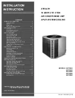
FIGURE 2 :
POSITIONING GROMMETS
TXV INSTALLATION
This condensing unit requires the installation of a thermal
expansion valve. The TXV controls the superheat of the
refrigerant at the outlet of the evaporator coil, ensuring the
proper refrigerant temperature at the suction of compressor.
Following are the basic steps for installing the TXV. For detail
instructions, refer to the Installation Instructions accompany-
ing the TXV kit.
Install TXV kit as follows:
1.
First, relieve the holding charge by depressing the
Schrader valve located in the end of the liquid line.
2.
After holding charge is completely discharged, loosen
and remove the liquid line fitting from the orifice distributor
assembly. Note that the fitting has right hand threads.
3.
Remove the orifice from the distributor body using a
small diameter wire or paper clip. Orifice is not used
when the TXV assembly is installed.
4.
After orifice is removed, install the thermal expansion
valve to the orifice distributor assembly with supplied fit-
tings. Hand tighten and turn an additional 1/8 turn to
seal. Do not overtighten fittings.
5.
Reinstall the liquid line to the top of the thermal expan-
sion valve. Hand modify the liquid line to align with cas-
ing opening.
6.
Install the TXV equalizer line into the vapor line as follows:
a.
Select a location on the vapor line for insertion of the
equalizer line which will not interfere with TXV bulb
placement.
b.
Use an awl to punch through the suction tube and
insert the awl to a depth to achieve a 1/8 inch diam-
eter hole.
7.
Install TXV equalizer line in 1/8 hole previously made in
vapor line. Equalizer line can be bottomed out in vapor
line as end of equalizer line is cut on 45 degrees angle to
prevent blockage. Braze equalizer line making sure that
tube opening is not brazed closed.
All connections to be brazed are copper-to-copper and
should be brazed with a phosphorous-copper alloy material
such as Silfos-5 or equivalent. DO NOT use soft solder.
Install the TXV bulb to the vapor line near the equalizer line,
using the two bulb clamps furnished with the TXV assembly.
Ensure the bulb is making maximum contact. Refer to TXV
installation instruction for view of bulb location.
a.
Bulb should be installed on a horizontal run of the
vapor line if possible. On lines under 7/8” OD the
bulb may be installed on top of the line. With 7/8"
OD and over, the bulb should be installed at the
position of about 4 or 8 o'clock.
b.
If bulb installation is made on a vertical run, the bulb
should be located at least 16 inches from any bend,
The evaporator coil is under 30 psig pressure.
UNIT
BASE
PAN
RUBBER
ELEVATING
GROMMETS
(4)
Note:DoNotblockdrainage
holeswithgrommets.
UNIT
BASE
PAN
RUBBER
ELEVATING
GROMMETS
(4)
WARNI
Dry nitrogen should always be supplied through the
tubing while it is being brazed, because the tempera-
ture required is high enough to cause oxidation of the
copper unless an inert atmosphere is provided. The
flow of dry nitrogen should continue until the joint has
cooled. Always use a pressure regulator and safety
valve to insure that only low pressure dry nitrogen is
introduced into the tubing. Only a small flow is neces-
sary to displace air and prevent oxidation.
In all cases, mount the TXV bulb after vapor line is
brazed and has had sufficient time to cool.
CAUTIO
CAUTIO


