035-15266-003 Rev. A (0804)
2
Unitary Products Group
GENERAL INFORMATION
EB FURNACE NOTES
The following list includes important facts and information
regarding the EB furnace and its packaging inclusions:
1.
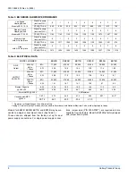
Furnace is rated at 240 volts, 60 Hz, single phase.
2.
Heating and Cooling thermostat is packed with furnace.
3.
Filters are furnished with each model.
4.
Filter size is universal to all models - 16 x 20 x 1.
5.
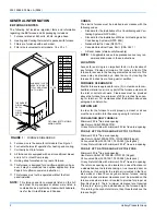
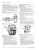
Furnace size is the same for all models. See Figure 1.
6.
Four-wire thermostat operation for heating and cooling.
7.
Coil cavity built into furnace.
8.
All furnaces are equipped with an air conditioner blower
and is A/C or Heat Pump ready.
9.
Holding strap furnished on top rear of furnace.
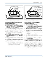
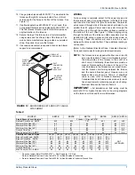
10. This furnace is designed for downflow application; how-
ever, it may be converted to an upflow application. (See
Page 6 for upflow conversion instruction.)
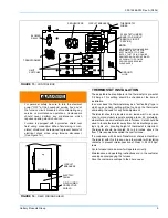
11. This furnace must not be operated without the front
panel installed.
NOTE:
This furnace and its components listed on the A/C
and Heat Pump equipment sticker were listed in
combination as a system by Underwriter's Laborato-
ries for the United States and Canada.
CODES
The electric furnace must be installed in accordance with the
following codes:
•
Standard for the Installation of Air Conditioning and Ven-
tilating Systems (NFPA 90A)
•
Standard for the Installation of Warm Air Heating and Air
Conditioning Systems (NFPA 90B)
•
National Electric Code (NFPA 70)
•
Canadian Electrical Code, Part I (CSA C22.1)
•
All local codes (state/county/township).
NOTE:
All applicable codes take precedence over any rec-
ommendation made in these instructions.
LOCATION
Access for servicing is an important factor in the location of
any furnace. Provide a minimum of 24 inches in front of the
furnace for access to the heating elements and controls. This
access may be provided by a closet door or by locating the
furnace 24 inches from a facing wall or partition.
FURNACE CLEARANCE
Electric furnace is approved for zero (0) in. clearance to com-
bustible material on all or any part of the furnace exterior and
the inlet or outlet duct work. Clearances must be provided
above the furnace for a minimum of 200 sq. inches free open-
ing for return air. For clearances other than shown above see
paragraph on Return Air.
RETURN AIR
In order for the furnace to work properly, a closet or alcove
must have a certain total free area opening for return air.
FOR HEATING ONLY FURNACE
Minimum 200 in
2
free area opening.
Use Return Grille 7900-287P/B,
Or any Return Grille with minimum 200 in
2
free area opening.
FOR A/C UP TO 4-TONS AND HP UP TO 3 1/2-TONS
Minimum 250 in
2
free area opening.
Use Return Grille 7900-287P/B, 1FG0620BK (hinged),
Or Louvered Door 3500-1581, 3500-5851 (bulk pack),
Or any Return Grille with minimum 250 in
2
free area opening.
FOR A/C UP TO 5-TONS AND HP UP TO 4-TONS
Minimum 330 in
2
free area opening.
Use Return Grille 1RF1025BK, 1FG0125 (hinged),
Or Louvered Door 3500-1591, 3500-5861 (bulk pack),
Or any Return Grille with minimum 330 in
2
free area opening.
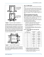
The return air opening can be located in a closet front door or
a sidewall above the furnace casing, or in a louvered door on
the furnace. If opening for the return air is located in the floor,
side walls or closet door anywhere below furnace casing
height, 6 inches minimum clearance must be provided on the
furnace side where return is located to provide for proper air
flow. See Figure 2. The 6 “ minimum clearance is not required
if there is a return grille installed above the furnace height.
This return grille cannot start more than three feet above the
furnace height.
FIGURE 1 :
FURNACE DIMENSIONS
51-5/8
19-5/8
SUB-BASE, IF USED,
ADDS 7/8” MORE TO
TOTAL HEIGHT AND
3/8” TO WIDTH.
THERMOSTAT
WIRING
ENTRY
FIELD
WIRING
ENTRY
OPTIONAL BOTTOM FIELD
WIRING ENTRY
A
B
C
D
E
F
H
G
J
K
L
M
N
1-7/8
2-5/8
3-1/2
1
5-1/16
5-1/2
1
5-13/16
1-3/4
7-13-16
8-5/8
9-7/16
16-1/2
J
H
C
B
A
D
E
F G
N
M
L
K


