Unitary Products Group
7
035-15266-003 Rev. A (0804)
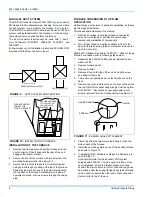
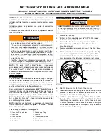
10. Flange plate shipped with 3500-7211* is mounted to the
furnace with eight (8) screws provided. Two (2) blunt
screws are for the holes in the front of the furnace. See
Figure 12.
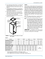
11. If upflow adapter box kit 3500-5451* is not used, then
our optional filter bracket is provided with 3500-7211* kit.
This filter bracket maybe used to retain filter inside its
original location in the furnace.
12. Secure the top of the furnace to a structural member
using screws and the strap on top of the furnace. The
mobile home manufacturer may provide an equivalent
strap, if required, to secure the furnace.
13. If excessive movement is expected, then some blower
support is recommended.
WIRING
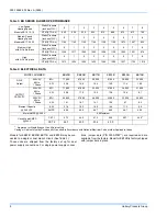
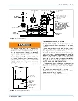
Furnace wiring is complete except for the power supply and
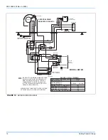
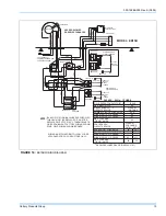
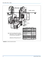
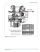
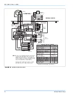
the thermostat wires. See wiring diagram (or Table 2) for wire
and fuse size. See Table 2 for ground wire sizes. Thermostat
wires connect through side of furnace and should also be no
smaller than 22 gauge. Power wires can enter through the
side of the unit or through the auxiliary entrance, located in
the bottom of the unit. (See Figure 1). When bringing wiring
through the bottom of the furnace, cable connectors must be
installed to hold wiring in place and to relieve any strain on
the wiring. These connectors will also serve as a seal
between the furnace and the floor. Thus, additional sealing is
not required.
(Refer to the National Electrical Code, Canadian Electrical
Code and local codes for wiring material requirements.
NOTE:
The furnaces are equipped with either one or two 60
amp circuit breakers. These circuit breakers protect
the wiring inside of the furnace in the event of a
short circuit. Additionally, these breakers provide a
means of disconnecting the power to the unit. The
circuit breakers in the furnace are not meant to pro-
tect the branch circuit wiring between the furnace
and the home's breaker panel. General wire and
breaker sizes are shown in Table 2. If sheathed
cable is used, refer to National Electrical Code,
Canadian Electrical Code and local codes for addi-
tional requirements concerning supply circuit wiring.
Electrical Data can be found in Table 4.
IMPORTANT -
All installation on field wiring must be
rated at 60ºC or higher. Please refer to the wiring diagrams
on the furnace or this book for more information.
*
Requires Jumper Bars (P/N 3500-3781*) - Dual Supply for U.S. Only.
Refer to National Electrical Code. Table 310-16 for Non-Sheathed Conductors.
+ Refer to National Electrical Code. Table 250-95 for Non-Sheathed Conductor Ground Wire.
FIGURE 12 :
BLOWER BRACKET AND DUCT FLANGE
ATTACHMENT
FLANGE
PLATE
(MOUNTED WITH
SCREWS)
EB SERIES
(UPFLOW
FURNACE)
DUCT
CONNECTOR
LINESET
KNOCKOUT
USE BLUNT
SCREWS HERE
Table 2:
MODELS
EB23B
EB20B
EB17B
EB15B
EB12B EB10B
Single Branch Circuit Service *
2 Leads + 1 Ground CKT#1
Nominal Circuit Load - AMPS
94.0
84.0
70.7
64.1
50.7
44.0
Minimum Wire Size (90º)
#2
#3
#4
#4
#6
#8
Minimum Wire Size (75º)
#1
#2
#3
#4
#6
#6
Minimum Wire Size (60º)
#0
#1
#2
#3
#4
#6
Ground Wire Size +
#6
#6
#8
#8
#8
#10
Max. Fuse (or C.B.) - AMPS
125
110
90
90
70
60
Dual Branch Circuit Service
CKT #1
CKT #2
CKT #1
CKT #2
CKT #1
CKT #2
CKT #1
CKT #2
NOT
APPROVED
Branch Circuit Load - AMPS
47.3
46.7
44.0
40.0
47.3
23.4
44.0
20.1
Branch Circuit Min. - AMPS
59.2
58.4
55.0
50.0
59.2
29.3
55.0
25.2
Minimum Wire Size (90º)
#6
#6
#8
#8
#6
#10
#8
#10
Minimum Wire Size (75º)
#6
#6
#6
#8
#6
#10
#6
#10
Minimum Wire Size (60º)
#4
#4
#6
#6
#4
#10
#6
#10
Ground Wire Size +
#10
#10
#10
#10
#10
#10
#10
#10
Max. Fuse (or C.B.) - AMPS
60
60
60
50
60
30
60
30


