Johnson Controls Unitary Products
3
18585-UAI-C-0708
MODIFICATIONS REQUIRED TO ADD A/C TO
EB FURNACES PRIOR TO AUGUST 1998 PRO-
DUCTION (If adding 3500-7901/* Blower)
1.
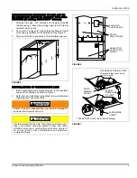
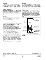
Drill eight (8) holes (.120” diameter) on the sides of the EB
furnace casing 2” above the existing upper row of holes for
coil shelf. See Figure 5.
2.
Cut a notch 7” wide x 3/4” high on the back flange of the fil-
ter housing to facilitate A-Coil installation. See Figure 5.
3.
Proceed with other instructions in this installation manual.
INSTALLATION OF CONDENSATE LINE
1.
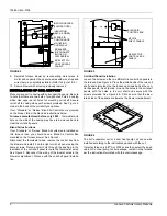
Install condensate drain pieces provided in this insulation
and coil shelf package as shown in Figure 7.
2.
Refer to A-Coil installation instructions for more information
regarding drain line connections.
FIGURE 5
Failure to install condensate trap can result in damage to
equipment and/or personal injury.
All areas around the line sets, drain hoses and other open-
ings in the furnace should be sealed air tight. Use some
moldable compound or caulking to seal the area. Failure to
do so may result in loss of performance and premature
compressor failure.
19”
2”
3/4”
7”
FIGURE 6
FIGURE 7
BLEND AIR
CONTROL BOX
EB ELECTRIC
CONTROL BOX
PANELS
EB COIL
SHELF PANELS
DRAIN
PRIMARY
OUTLET
ELBOW
DRAIN TUBE
& CLAMP
SECONDARY DRAIN OUTLET
(Knockout along score line to
remove insert)
LARGE HOSE
CLAMP**
** PACKED WITH COIL (Small Parts Package)

