


4-18
PowerWAVE 9000 DPA UPS - Operation
(Issue 2.1 Oct. 2009)
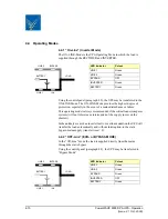
4.8 Transfer From Maintenance Bypass
This procedure describes the sequence of operations to be done in order to
restart the UPS and restore ON-LINE mode (Load on Inverter).
ALL THE OPERATIONS IN THIS SECTION MUST BE PERFORMED BY
AUTHORISED ELECTRICIANS OR BY QUALIFIED INTERNAL
PERSONNEL.
UPS system status prior to transfer
The load is supplied directly by Input Mains power and the UPS is OFF.
1.
Close battery fuses/breakers in the external battery cabinets or racks.
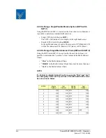
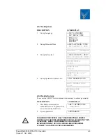
2.
The LCD panel will indicate: “LOAD OFF, SUPPLY FAILURE” will
appear. The LED display will give the following indications:
3.
Close Parallel Isolators IA2-1, IA2-2, IA2-3, IA2-4 and IA2-5 and
check message "PARALLEL SW CLOSED" on LCD of each
module.
4.
Simultaneously press both ON/OFF buttons on the UPS control panel
(PMD) on all three control panels.
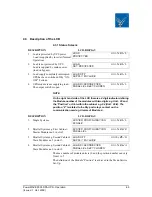
Unit will start-up and after about 60 seconds, the LED display will
give the following indications:
5.
Make sure that the bypass LED is green on all modules, then open the
Maintenance Bypass Switch IA1 (position OFF).
6.
Using LCD panel on any module, select the COMMANDS menu and
choose command “LOAD TO INVERTER”. This will transfer the
LOAD to Inverter on the complete system. On LCD panel “LOAD
PROTECTED” will appear.
LOAD IS NOW SUPPLIED BY INVERTER AND IS PROTECTED
LED Indicator
Colour
LINE 1
Green
LINE 2
OFF
BYPASS
OFF
INVERTER
OFF
BATTERY
Flashing Green
LED Indicator
Colour
LINE 1
Green
LINE 2
Green
BYPASS
Green
INVERTER
Red
BATTERY
Green


