
3-16
PowerWAVE 9000 DPA UPS - Installation
(Issue 2.1 Oct. 2009)
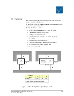
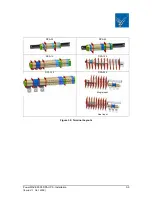
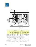
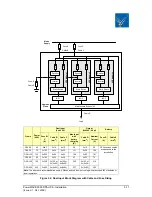
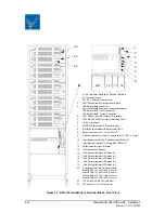
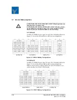
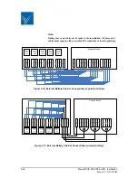
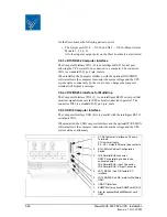
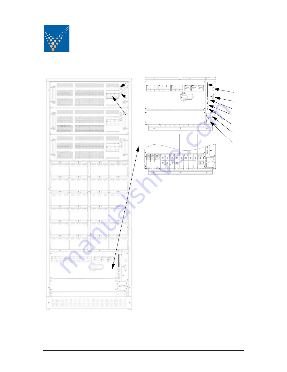
Figure 3.9: DPA-150 Input/Output Terminal Block, Front View
1.
X1-X4 Customer interface on Phoenix Terminals:
X1 Customer Inputs
X2…X4 = Potential free contacts
2.
SW1-9 Multi-Cabinet Configuration Switch
3.
JD8 Parallel BUS connector
Only for paralleling cabinets use optional adapter:
JD5 Parallel BUS - Input Connector
JD6 Parallel BUS - Output Connector
4.
JD11 RS232 / Sub D9/ female, PC interface
5.
JD12 RS232/ Sub D9 / male for Multidrop ONLY
6.
USB PC Interface
7.
SNMP Slot for optional SNMP card ONLY
8.
Slot for optional Modem/Ethernet card ONLY
9.
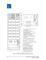
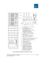
Battery te / N / - for 16/25 mm
2
10.
Input Bypass terminal for Dual Input feed 3xM10
11.
Input Rectifier terminal for Single feed 4xM10
12.
Output Load terminal 4xM10
13.
IA1 Maintenance Bypass
14.
IA2-1 Parallel Isolator UPS-Module 1
15.
IA2-2 Parallel Isolator UPS-Module 2
16.
IA2-3 Parallel Isolator UPS-Module 3
19.
F4 Battery Fuse Holder Module 1
20.
F4 Battery Fuse Holder Module 2
21.
F4 Battery Fuse Holder Module 3
22.
F2 Bypass Line Fuse on each module
Module DPA 30 22x58 / 50A Pronorm
Module DPA 40 22x58 / 63A Pronorm
Module DPA 50 22x58 / 63APronorm
23
JD1 Smart Port- RS232 (Sub-D9P)
24
JD7 Connector for Control Panel
1
2
3
4
5
6
7
8
9
10 11
12
23
24
22
19
20
21
14 15 16
13


