

3-8
PowerWAVE 9000 DPA UPS - Installation
(Issue 2.1 Oct. 2009)
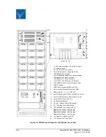
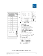
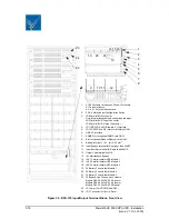
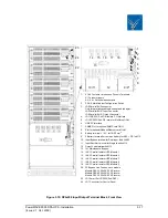
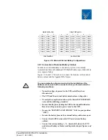
Remove the terminal cover of the UPS.
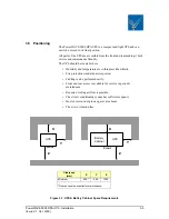
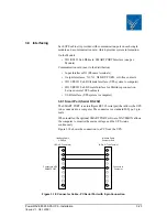
Connect the output power cable coming from the LV-Distribution Board to
the terminals of the UPS (Figure 3.5).
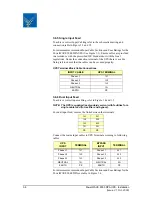
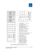
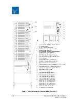
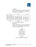
3.6.9 Output Cabling
For output cabling connect output cable to UPS Terminal according
to following Output to UPS terminal block correlation.
There is a cable-fixing rail under the connection terminals of the UPS to
ensure the cables are properly fastened.
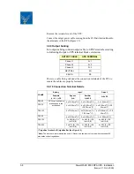
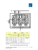
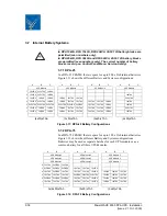
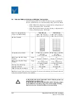
3.6.10 Connection Terminal Details
OUTPUT CABLE
UPS TERMINAL
Phase L1
3L1
Phase L2
3L2
Phase L3
3L3
NEUTRAL
3N
EARTH
PE
FRAME
Battery
Input*
Output*
Separate
(+ / N / -) +PE
Bypass
3+N
Rectifier
3+N+PE
3+N+PE
DPA-25
DC Fuses and cables
are bespoke to the
installation
.
4 x 10/16mm
2
(T)
5 x 10/16mm
2
(T)
5 x 10/16mm
2
(T)
DPA-75
4 x 35/50mm
2
(T)
4 x 35/50mm
2
(T)
+PE 50mm
2
(T)
4 x 35/50mm
2
(T) +PE
50mm
2
(T)
DPA-125
4 x 70/95mm
2
(T)
4 x 70/95mm
2
(T) +
PE 50mm
2
(T)
4 x 70/95mm
2
(T) + PE
50mm
2
(T)
DPA-50
4 x 16/25mm
2
(T)
5 x 16/25mm
2
(T)
5 x 16/25mm
2
(T)
DPA-150
3 x M10(B) +PE
1xM10 (B)
4 x M10 (B) +PE
1xM10 (B)
4 x M10 (B) +PE
1xM10 (B)
DPA-250
3 x M12 (B) +PE
1xM12 (B)
4 x M12 (B) +PE
1xM12 (B)
4 x M12 (B) +PE
1xM12 (B)
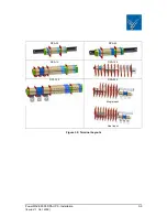
(T) signifies Terminals. (B) signifies Bar (See Figure 3.2)
*Note:
The above are recommendations only. All fuses and cables must comply with prescribed IEC
standards or local regulations.


