background image


Appendix A: Specifications


31 

APPENDIX A: SPECIFICATIONS 

General 

Functionality 

Real-time AUX channel traffic capturing, decoding and display. 
Data store and reload in binary format. 
HTML report generation. 
Internal 14 MByte capture buffer. 

AUX transactions as fast as 0.5 ms per transaction (R Reply). 
Input state changes monitored up to 8000 changes / s. 
Timestamps with 32 µs resolution. 


Operating Systems 

Windows® 10, 8, 7 


Mechanical size 

105 x 130 x 35 mm 

Weight 

260 grams 

Power Consumption  5 V, 400 mA 

Interfaces 

Features: 


DisplayPort™

 Interfaces 

One DisplayPort™ 

receptacle input connector. 

One DisplayPort™ 

receptacle output connector. 

AUX channel and HPD signals pass-through. 
DPA-400: Main stream lanes buffered with 1:1 amplification 

(maximum bandwidth 2.7 Gbps).  
Pin 20 (DP_PWR) pass-through 

DPA-400 1.2 and later: Main stream lanes by-passed with 

the provided cable.  
Pin 20 (DP_PWR) not connected 

Custom I/O 


Sub-D 9 socket (female). 
3 trigger inputs, link HPD signal. 
4 expansion outputs. 
ESD protection on all external signals. 

PC Interface 

USB interface, USB-powered. 
Software upgrade capability through USB 


Electrical characteristics: 


Trigger inputs 

5V tolerant. 

3.3V CMOS input levels. 
IEC 61000-4-2 (ESD) 8kV (air), 6kV (contact) 

DisplayPort™

 signals 

IEC 61000-4-2 (ESD) 8kV (air), 6kV (contact) 


Summary of Contents for DisplayPort DPA-400

Page 1: ...DPA 400 DisplayPort AUX Channel Monitor USER MANUAL...

Page 2: ...Monitor User Manual Version 10 Document identifier KH65920 Date 16 December 2019 Company information Unigraf Oy Piispantilankuja 4 FI 02240 ESPOO Finland Tel 358 9 859 550 info unigraf fi https www u...

Page 3: ...he Main Window 15 Controlling the Acquisition 16 Starting and Stopping Data Acquisition 16 Monitored Signals 17 Acquiring Data 18 Decoding the Data 19 Inspecting the Acquired Data 20 Lines 20 Columns...

Page 4: ...annel monitor DPA 400 setup procedure Serial Communication and License Key Setup Run the DPA 400 Setup installer Plug the USB connector of the DPA 400 to one of the USB ports in your PC Launch the DPA...

Page 5: ...of the DPA 400 and of its features Guide to the DPA 400 typical usage Product Versions Functionality and operation described in this manual is related to software release 1 7 Please contact Unigraf fo...

Page 6: ...mented by a time stamp marking each of its changes of state Easy to Use The DPA 400 is a USB powered device and measures only 10 5 x 13 x 3 5 centimeters making it an ideal tool for a laboratory deskt...

Page 7: ...also select one or more of the external input signals or the HPD for being monitored Every logical state change of the monitored signals is recorded together with the timestamp of when it happened Thi...

Page 8: ...C and LTTPR specific DPCD registers DPA product delivery contains a custom Y shaped cables for use with DP 1 2 and later versions The custom cables bypass the main links outside DPA 400 as shown in th...

Page 9: ...its Windows driver will be installed as a virtual serial port named as a DPA 400 USB Serial Port Please use the USB Serial Port driver installed by DPA 400 installer Note System administrator s privil...

Page 10: ...e firmware in the DPA 400 unit you have to set up the COM port used and provide the license code delivered with the unit Selecting the COM Port Used From the GUI pull down menu in the center of the GU...

Page 11: ...nd your DPA 400 License Key on a sticker glued on its enclosure in the delivery package or among its related documents If you cannot locate the License Key please email to Unigraf the Seed Number show...

Page 12: ...hat various features of DPA 400 are enabled with license keys For upgrading your DPA 400 please contact Unigraf Note The License Key never includes characters I G B O because of their similarity with...

Page 13: ...raf DPA 400 Firmware In this directory you should find the updater UUFUpd exe and the FW file e g dpa 400 uuf In Windows command prompt run uufupd c 3 f dpa 400 uuf In the entry please substitute 3 wi...

Page 14: ...g Ready Plug your DPA 400 to your PC and start the GUI application Verify that the right COM port is selected a valid License Key is available and the GUI main window opens If required connect your ex...

Page 15: ...ction line The Start acquisition button controls the start and stop of the data acquisition The Status line at the bottom of the window shows the current GUI state the amount of data already downloade...

Page 16: ...e advanced options Start on the rising or falling edge of HPD signal Start on the rising or falling edge of IN0 signal Start on the rising or falling edge of IN1 signal Start on the rising or falling...

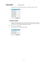
Page 17: ...dition to the AUX channel traffic you can also monitor the status of four digital signals By default only the HPD signal is monitored In the Monitored signals dialog you can include also one or more o...

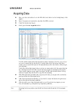
Page 18: ...d as zero meaning that all of the acquired data has been downloaded to the GUI When a quick and long sequence of transactions is acquired or when a rapidly toggling external input is monitored the DPA...

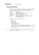
Page 19: ...P 2 0 support for DPCD 1 4 decoding including DSC FEC and LTTPR specific DPCD registers From the pull down menu select Decoding and select the version You can select DPCD 1 1 Decoder DPCD 1 2 Decoder...

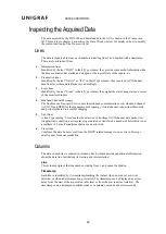
Page 20: ...band communications over sideband channel AUX CH and HPD for the management of topology virtual channel connection Main Link and performs Main Link symbol mapping 5 Error lines A line Type reading Err...

Page 21: ...Native marks Native AUX channel Requests and Replies I2C marks I2C AUX channel Requests and Replies Sideband Request and Sideband Reply to mark the Sideband Channel messages Event is used for signal...

Page 22: ...list For AUX channel transaction lines for each of the DPCD memory locations affected the panel lists All data bytes read or written All DPCD memory locations affected The name of the locations and o...

Page 23: ...rs directly but make copies of them In the Stored custom filter definitions panel you will have the list of currently defined Filters On the right hand side buttons you can define new Filters rename o...

Page 24: ...nd gradually add new rules while testing their performance Note Filtering and selecting the columns for display do not affect the actual data acquisition All transactions and their full data are alway...

Page 25: ...mouse over the list From the pop up menu you can choose which columns to display the style of the timestamp and switch between absolute and relative timestamps Selecting Font and Colors You can select...

Page 26: ...f the range that you want to be colored Press Accept Select the range you just created from the Colored addresses ranges list and click the Font Color and Background Color buttons to select the colors...

Page 27: ...selected DPCD location Use Search Find or press Ctrl F In the Search dialog select the access type and the DPCD location address that you want to search The first occurrence of the found access is sel...

Page 28: ...nerator that creates a test report of the results displayed in the Results Grid The report is generated in HTML format and includes a detailed description of the test steps executed the actions taken...

Page 29: ...previously acquired data that has been saved in binary format Use first File Load and then File Save Report Note Report creation for large amounts of acquired data can generate large HTML files and ta...

Page 30: ...SAVING YOUR DATA 30 In order to print the report scroll down and click the Show printer friendly format pushbutton to get a new view formatted for an easy printing...

Page 31: ...terfaces One DisplayPort receptacle input connector One DisplayPort receptacle output connector AUX channel and HPD signals pass through DPA 400 Main stream lanes buffered with 1 1 amplification maxim...

Page 32: ...also available on this connector to provide you an easy measurement access to the HPD signal driven by your DisplayPort sink and connected to your DisplayPort source device Pin Signal Name Direction...

Page 33: ...s determined as not matched The wildcard can be used to allow data blocks of any size to match Whitespaces and new lines are ignored and are allowed anywhere White spaces and new lines can be used str...

Page 34: ...ata byte ending to 10 11 01 but not 00 To match a single data byte with more than one value separate the values with comma 0 1 100 200 254 Matches a data byte whose value is 0 1 100 200 or 254 Invert...

Reviews: