background image

28


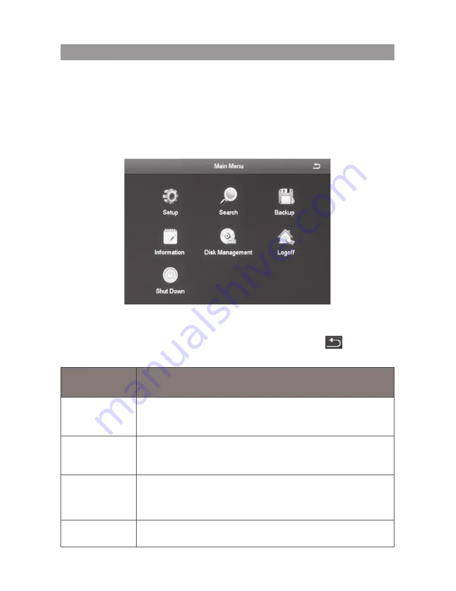
The main menu screen displays icons that represent various system operations. 

Click on an icon to configure, operate, and maintain the gDVR system. 

Appendix A: Menu Structure shows how the menu, screens, and 

tabs for screens are organized in the system. 

From the 

system

 menu, select 

Main Menu

 (see page 26). The 

Main Menu


screen displays. 

Click on the 

Main Menu

 icons to select a particular feature. Icons, submenus, 

or screens display to help you manage the system. many of these screens 

have tabs across the top to further refine operations. Click the 

 icon to 

return to the previous screen.

MaIn Menu 

Icon

DescrIptIon

Setup

Click on 

setup

 and 9 icons display on the 

setup

 screen. 

These icons lead you through configuring your system. 

See page 29 for icon and screen details.

Search

Select 

search

 to display a 4-tab screen to set search 

parameters and search for specific recorded files. See 

page 62 for icon and screen details.

Backup

The

 Backup

 screen lets you set specific time ranges on 

specific cameras for backup. See page 66 for icon and 

screen details.

Information

Click on 

information

 to view 6 types of system information. 

See page 67 for icon and screen details.

Main Menu oVerVieW

Summary of Contents for GDVR 4A Series

Page 1: ...GdVr 4a 8a series security system OWNER S Manual For more exciting new products please visit our website australia www uniden com au ...

Page 2: ...lert the user to the presence of uninsulated dangerous voltage within the product s enclosure that may be of sufficient magnitude to constitute a risk of electric shock WarninG to PreVent Fire or sHocK HaZard do not eXPose tHis unit to rain or Moisture In addition to the careful attention devoted to quality standards in the manufacturing process of your product safety is a major factor in the desi...

Page 3: ... humid or wet places 4 Keep enough space around the product for ventilation Slots and openings in the storage cabinet should not be blocked 5 It is highly recommended to connect the product to a surge protector to protect from damage caused by electrical surges It is also recommended to connect the product to an uninterruptible power supply UPS which has an internal battery that will keep the prod...

Page 4: ...amage or deteriorated insulation have it replaced by your service technician 6 Power Cord Protection Power supply cords should be routed so that they are not likely to be walked on or pinched by items placed upon or against them Pay particular attention to cords at plugs convenience receptacles and the point where they exit from the product 7 Surge Protectors It is highly recommended that the prod...

Page 5: ...n cable s to verify compliance with your local authority regulations prior to installation 14 Mounting The cameras provided with this system should be mounted only as instructed in this guide or the instructions that came with your cameras using the provided mounting brackets 15 Camera Installation Cameras are not intended for submersion in water Not all cameras can be installed outdoors Check you...

Page 6: ...afety checks recommended by the manufacturer to determine that the product is in safe operating condition Use 1 Cleaning Unplug the product from the wall outlet before cleaning Do not use liq uid cleaners or aerosol cleaners Use a damp cloth for cleaning 2 Product and Cart Combination When product is installed on a cart product and cart combination should be moved with care Quick stops excessive f...

Page 7: ...Find and View Shapshots 17 Mask Motion Sensitive areas 17 Set Up Email Notification and Alert 18 Configure Alarms 18 Create a Recording Schedule 18 Transfer Recorded Files 18 Add or Change a Password 18 GUARDIANlive APP 19 USING THE APP 19 Basic Operation 24 System login 24 Live VIEW 24 SYSTEM menu 26 Main menu OVERVIEW 28 SETUP ICON 29 Basic Screen 29 Live Screen 33 Record Screen 37 Schedule Scre...

Page 8: ...tem Screen 68 Event List Screen 68 Log list Screen 69 Network Screen 69 Online Users list Screen 70 Exit Screen 70 Disk Management ICON 71 LOG OFF ICOn 72 Shut Down Icon 72 Remote Access 73 FIRMWARE UPDATES 74 TROUBLESHOOTING 75 APPENDIX A MENU STRUCTURE 79 APPENDIX B Hard Disk Capacity Calculation 80 SPECIFICATIONS 81 WARRANTY 84 ...

Page 9: ...eillance network Its professional network video surveillance software provides strong network communication and telecommunication ability ABOUT THIS MANUAL This OM provides operating procedures for the GDVR AHD system The GDVR AHD models operate identically There are only 2 differences between the models the number of channels and the number of cameras GDVR 4A22 2 outdoor cameras 2 indoor cameras ...

Page 10: ...0 1 4 GDVR 4A22 1 2 2 GDVR 8A42 1 4 2 With 1TB HDD With 1TB HDD Each DVR comes with 7 Video Power cable 8 AC Adaptor 9 Mounting Screws and Hex Keys not shown here 1 2 3 4 5 7 8 1 Power Splitter Cable 2 AC Adaptor 3 HDMI Cable 4 Mouse 5 Ethernet Cable 6 Remote 6 Each Camera comes with ...

Page 11: ... LED HDD LED USB Port ALARM IN OUT VIDEO IN VIDEO OUT AUDIO OUT HDMI AUDIO IN USB Port RS485 RJ45 DC12V VGA cameras external speaker external display mouse external HD AC Adaptor external display ethernet cable If using PTZ cameras Front Back ...

Page 12: ...now Your Cameras Infra red LEDs Camera Lens Light Sensor Light Sensor Camera Lens Infra red LEDs BNC Video Connector Green Power Connector Red Power Connector Red Indoor Camera Outdoor Camera BNC Video Connector Green ...

Page 13: ...er cable 4 Connect the HDMI cable supplied to the HDMI port on the DVR and to the external display device TV PC or use the VGA cable not supplied for the VGA port 5 Connect the Mouse to one of the USB ports on the DVR installation HDMI Cable External Display Mouse Ethernet Cable Modem Router AC Adaptor Power Outlet Video Power Cable Power Splitter Cable DVR Camera AC Adaptor Power Outlet Follow th...

Page 14: ... on the DVR and to your modem router for remote viewing 7 Connect the Power Splitter cable to the camera s AC adaptor which connects to a power outlet 8 Plug the DVR s AC Adaptor jack into the DC12V port on the DVR and the other end to a power outlet ...

Page 15: ...u made in the previous step See page 54 to set up a password It is strongly recommended that you add a password to the admin account and to all other accounts you may add to the system Required Settings Set the system date and time so recorded files will be correctly time stamped Next create a password for the admin user Set Date and Time The correct date and time are critical for the timestamp on...

Page 16: ...word field See page 54 for a detailed description on how to set up a password Default Operation Settings Uniden s default settings allow you to begin monitoring your network immediately After you have monitored your network for a week or two you may find you need to slightly adjust your settings For example you may need to mask areas from motion detection trees etc ...

Page 17: ...nsor sensor triggered or all triggered files 3 From the Main Menu Information Event List set up the time frames and cameras you want to search and whether you want to search for Motion Sensor or Video Loss this screen is similar to the Search screen above Select Search tab and records that meet those criteria display Set Up Alarms and Alarm Notification Main Menu Setup Alarm OtherAlarm Play Back R...

Page 18: ...ideo Loss or Other Alarm Create a Recording Schedule Main Menu Setup Schedule You can set up recordings by a specific calendar schedule or according to sensor type Transfer Recorded Files from the Hard Drive to a USB Device Main Menu Setup Advanced Import Export tab Add or Change a Password Main Menu Setup Users User Management Change Password field ...

Page 19: ... name and password again and the Device List screen displays 4 Select the icon at the top right corner to add your DVR system to the app The add Device screen displays 5 Name your DVR system Select the QR code icon and scan the QR code label on top of the DVR receiver or the applicable Device ID QR code from Main Menu information system screen on the monitor This will add the DVR Device ID code to...

Page 20: ...20 LIVE SCREEN Live Screen is the main screen in the GuardianLive app Quad View Pause Microphone Audio HD SD Alarm Refresh Snapshot Remote Playback Record Back Camera Name Date Time display ...

Page 21: ...nt take a snapshot of and then tap the snapshot icon Recording Tap the camera view that you want to record and then tap the Record icon Mic Tap to record sound HD SD Tap to view either in High Definition or Standard Definition Refresh Tap to refresh live view Playback Tap to playback recorded video Alert SCREEN On the app in the live view tap the Alert icon to get the Alarm screen displayed Tap th...

Page 22: ... options About Recordings Snapshots and Logout Tap the option Recordings to view the recordings that have been initiated on the app Please note these recordings are NOT stored on the hard disk REMOTE PLAYBACK SCREEN On the app in the live view tap the Playback icon to get the Remote Playback screen displayed Tap the date displayed on the top right corner of the screen to get the Select Date pop up...

Page 23: ...e Menu icon top left corner to reveal menu options About Recordings Snapshots and Logout Tap the option Snapshots to view the images that have been taken using the app Please note these images are NOT stored on the hard disk Logout Tap to logout of the app ...

Page 24: ...ou made in the previous step See page 54 to set up a password It is strongly recommended that you add a password to the admin account and to all other accounts you may add to the system Live VIEW Live view displays video images from all 4 cameras The date time and camera number display in each viewing window The recording and alarm status icons display in the lower left hand corner of each window ...

Page 25: ...tion detection recording Blue Schedule recording Red Alarm recording motion Detected This icon displays when the camera for that view detects motion Audio Recording On need external microphone to record audio not provided Network Disconnected DD mm yyyy hh mm SS Date and Time Stamp for recorded files ...

Page 26: ... Menu Item Description Single Select a camera to display in full screen Double click the left mouse button to return to Multi channel mode Multi Select this menu option from Single channel mode to display all 4 or 8 cameras in Multi channel mode Start Scan Stop Scan Turn Scan operation on and off You must first set up scanning parameters such as how long a specific camera displays before moving to...

Page 27: ... whereby audio will be played automatically for any channel that is brought up to full screen PTZ This icon control a Pan Tilt Zoom PTZ camera if installed not included It can set the PTZ camera s address Baud rate and Protocol and help you set camera movement patterns Snap The GDVR can take snapshots of live video A camera icon displays Start Record Stop Record Start and stop recording for all ch...

Page 28: ...s across the top to further refine operations Click the icon to return to the previous screen MaIn Menu Icon DescrIptIon Setup Click on setup and 9 icons display on the setup screen These icons lead you through configuring your system See page 29 for icon and screen details Search Select search to display a 4 tab screen to set search parameters and search for specific recorded files See page 62 fo...

Page 29: ...ls Logoff This selection logs you off of the GDVR system See page 72 for icon and screen details Shutdown This selection powers off the GDVR See page 72 for icon and screen details SETUP ICON Select the Setup icon and the Setup screen displays 9 options that help you configure and set up your system Basic Screen The Basic screen contains three tabs System Date Time Daylight Saving Time DST ...

Page 30: ...PAL format default PAL Password Check Keep checked to require a password to log in Show System Time Choose whether to display time in the field or not Max Online Users Set the number of network users visiting the device Video Output User can select VGA 800x600 1024x768 1280x720 1280x1024 output mode Language Select display language Logout After Minutes When there is no action after this set time t...

Page 31: ...ect Sync Time with NTP Server to correct time Network server time can be set Field Description Date Format Set date format Time Format 12 or 24 hour format Time Zone Set time zone in GMT format Sync Time with NTP Server Check box to select time sync uncheck box to deselect NTP Server Select Update Now to sync time System Date Set date through pop up calendar System Time Set time ...

Page 32: ... ability to keep track of DST on or off Time Offset Hours Select 1 or 2 hour offset Mode Set DST by week or by actual date From Set DST beginning date Always the first Sunday of October offset 1 hr If Mode Week set DST by month number of week day of week and hours to be offset i e the 1st Sunday 1 hour offset If Mode Date set DST by date according to popup calendar ...

Page 33: ...pril the 1st Sunday 1 hour offset If Mode Date set DST by date according to popup calendar Default Select Default to use the automatic DST default values Apply Select Apply to use the values you just manually set Exit Leave the screen without making changes Live Screen The Live screen establishes how the screen looks when in Live view It has 3 tabs Live Main Monitor Video Blind ...

Page 34: ...ame the camera and set up how the image displays colour contrast etc 1 Select a camera to rename A keyboard displays 2 Rename the camera and select Enter 3 Select Setting for that camera A selection screen displays on the live video screen 4 Adjust the brightness hue saturation and contrast of the corresponding channel and select Ok 5 Select another channel to adjust When you are finished select O...

Page 35: ... displays on the screen s sections You can also set how long the video pauses on each image before moving to another image 5 to 60 seconds in 5 second intervals Video Blind Masking Tab You can mask off up to 4 rectangular areas in a single screen No video records from those masked off areas only a blank box rectangle displays ...

Page 36: ...overs the area you indicated Release the mouse 3 Right click to return to the Video Blind tab Select Apply to save your settings 4 Repeat Steps 2 and 3 up to 3 more times 4 areas selected per screen 5 To remove video masks double click on the area you want to remove the white rectangle changes to black 6 Right click to return to the Video Blind tab Select Apply to save your settings The masked are...

Page 37: ...termine if the selected camera will record video or audio or both Field Description Record Check to set the channel to record video Uncheck to skip recording video for this channel Audio Check to set the channel to record audio Uncheck to skip recording audio for this channel for audio recording use external microphone not provided All Apply selections to all channels ...

Page 38: ... lower Otherwise there will not be enough room on the hard drive to save the recorded file Field Description Resolution Supports both 720P AHD camera and 960H analog camera resolution Default 720P FPS Range 1 25 Default 25 fps Encode Support VBR Variable Bit Rate and CBR Constant Bit Rate Default Variable Bit Rate Quality The higher the quality is the clearer the video images are Max Bitrate 256 k...

Page 39: ...splay the time on this channel Position Move the date time block to a different area of the screen 1 Select Setting on the Stamp tab Live video displays for that channel along with the date time block in a small text frame 2 Left click and hold over the date time block Move the block to where you want it to display Release the mouse and right click to return to the Stamp tab 3 Select Apply to save...

Page 40: ...box is not checked not enabled the system stops recording and displays an information message Snap Tab Snapshot In this tab the user can set the resolution image quality level time interval of snapshot and the number of snapshot for one time Field Description Resolution CIF Snap Time Interval Time interval between snapshots Snap Number Number of snapshots taken at one time ...

Page 41: ...r channel select that channel in the dropdown box for apply settings To Then select copy The configuration is now copied to the second desired channel 6 If you want to apply the settings from one channel to ALL channels select all in the dropdown box for apply settings To Then select copy The configuration is now copied to all channels 7 Select apply to save the settings 8 Select Exit Motion Tab T...

Page 42: ...ed 1 Select a channel whose sensor recording schedule you want to set up 2 Select the erase icon and click on the 1 hour recording blocks you DO NOT want that channel to record 3 Select one hour blocks to remove from the recording schedule 4 When you have the schedule set up as you want it select apply The configuration for that channel is now saved 5 To use that same configuration on another chan...

Page 43: ...ion Establish parameters for motion detection as well as a motion detection operation schedule Video Loss Set up an alarm notification plan if any cameras lose video Other alarm Establish alarm system for other types of alarms not previously covered Sensor Icon The Sensor screen enables or disables sensor operation for a specific channel This screen has three tabs Basic Tab Alarm Handling Tab Sche...

Page 44: ... sec 10 sec 20 sec 30 sec 60 sec 120 sec or Always Trigger Select this field to set alarm trigger configuration trigger recording PTZ camera linking PTZ camera not included etc Selecting this field displays the Trigger screen for a specific channel Name Name the alarm Trigger Channel X Screen You may reach this screen from other tabs It lets you set up what happens when an alarm is triggered the c...

Page 45: ...s to optional alarms not included added to the system Email When enabled and an alarm is triggered the system sends information relevant to the alarm alarm event device name etc to the user specified mailbox Snap When enabled and an alarm is triggered the system automatically takes a snapshot of the selected channel and stores it on the hard disk To PTZ Set PTZ movement parameters Only applies if ...

Page 46: ...led not included Sets what type of action to take Preset Cruise Track None Sets which point the PTZ camera will rotate to if preset selected Schedule Tab Use this tab to set a time frames for the alarms to be active This tab operates in the same way as the Sensor tab See page 41 for details on setting up a schedule ...

Page 47: ...0 sec 30 sec 60 sec and 120 sec or Always Trigger The Trigger screen is the same as on page 45 Area Commonly called motion masking a grid overlays a selected camera s live video with task bar at the bottom Mask off areas the motion detection ignores You can also determine motion sensitivity block off ceiling fans or the floor area if you have pets In this interface the user can drag the scrollbar ...

Page 48: ...ppropriate or not Save the settings exit schedule tab Use this tab to set a time frames for the alarms to be active This tab operates in the same way as the Sensor tab See page 41 for details on setting up a schedule Video Loss Icon If you lose video from a camera someone cuts the cable the system alerts you according to the presets from this screen ...

Page 49: ...rk Address Conflict Disconnection HDD Attenuation Warning Disk Loss Buzzer The system emits 2 long beeps when an alarm occurs Not available on all models Email When enabled and an alarm is triggered the system sends information relevant to the alarm alarm event device name etc to the user specified mailbox To Alarm Out When enabled triggers will send an alarm to the specified alarm output Disk Sho...

Page 50: ...rt Default 80 Server Port Default 5000 Mobile Port Default 5001 Obtain an IP Address Automatically Default Checked You must have DHCP turned on in your router Typical default setting IP Address IP address of the device Subnet Mask Device s subnet mask Gateway Device s default gateway Preferred DNS Server The address is provided by your network operator and must be filled in when using mobile monit...

Page 51: ...ervice Provider Password Enter the set password Test Click Test and it will check that the IP address and PPPOE information are valid Sub Stream Tab This screen sets the type of video you receive on your mobile device Field Description Resolution Supports CIF FRS Choice range 1 6 Encode Support VBR and CBR Default VBR Quality Select one of the following quality levels Lowest Low Medium Higher ...

Page 52: ...eld Description STMP Server Mail server address can be IP address and domain name if domain name confirm that the DNS setting is right then it can be correctly resolved e g smtp gmail com Port Mail server port number Default 465 SSL Check Provides secure socket layer for login Send Address Mail server s email address Password Password corresponding to sender s email password Receive Address When a...

Page 53: ...ers The admin user does not have a password Uniden strongly recommends that you add a password to the admin user account Adding a User Select the Add button at the bottom of the screen to display the Add User screen This screen has 2 tabs General Initial user setup User name password user type etc Authority Grants new user access to specific elements of the system Remote login manual record remote...

Page 54: ...onnected Enter all zeros to lift this restriction and make access available to any PCs NOTE If a computer s physical address is 0 the GDVR system does not bind to a specific computer and the user can use any computer to log into the client to use the DVR However once a specific computer s physical address is entered the user can only use that specific computer to log in to the client to use the DV...

Page 55: ...ecific computer and the user can use any computer to log into the client to use the DVR However once a specific computer s physical address is entered the user can only use that specific computer log into the client to use the DVR Deleting a User 1 Select a user from the User Management screen 2 Select Delete The system displays a confirmation message 3 Confirm deletion Changing a Password 1 Selec...

Page 56: ... optional PTZ camera Tabs in this icon help you set movement patterns These patterns are Presets move the camera from point A to point B Cruise move the camera through multiple points or Track Serial Port Tab Field Description Enable Check this field to turn on the camera for that channel Address PTZ device address ...

Page 57: ... VIDO DSCP VISCA SAMSUNG RM110 HY N control Simulative Cruise Allows the camera to use cruise patterns whether the camera supports PTZ cruise functions or not Advanced Tab This tab helps you create name and save PTZ movement patterns for a specific channel These patterns are Presets move the camera from point A to point B Cruise move the camera through multiple points or Track You can create up to...

Page 58: ...elected channel In the Preset column select Setting for the channel you want to work with The Preset Channel X screen displays Preset Channel X Screen This screen helps you create name and save a PTZ configuration for a specific channel You can create up to 128 PTZ configurations for a channel 1 Click Setting A pop up toolbar displays in the bottom of live video 2 Adjust PTZ to the appropriate loc...

Page 59: ... You can set a maximum of 128 preset points Cruise Channel X Screen Select Setting under the Cruise column for a specific channel and the Cruise Channel X screen displays You can create up to 8 PTZ cruise selections per channel 1 Select Add to add up to 8 cruise lines 2 Double click one of the entries and the Cruise Preset screen displays ...

Page 60: ...ield displays Add preset point Delete the preset point modify the selected preset point Start Recording Controls PTZ recording tracks Wiper Control Start Track execute the recorded tracks Control external IR devices hide function Adjust PRZ direction ...

Page 61: ...ails as follow Button FunctIon Button FunctIon Play Pause Next Frame Fast Forward Previous Frame Play previous file Playback Single screen display Play next file multi Screen Display Select Pause to advance the recorded video frame by frame advanced icon Select the advanced icon the advanced setup screen displays 3 icons Reset Return all settings to factory defaults Import export export system par...

Page 62: ...rch specific channels for recorded events during specific start and end times File Management Once you have located files for a specific time period you can select those files for deletion or lock them to prevent them being deleted Image Search for snapshots Time Search Tab Use this tab if you need to check video for a specific time frame 1 On the right side of the screen there is a calendar and a...

Page 63: ...specific types of events for predetermined dates channels 1 Select a date to search as well as indicate what channels you want to include in the search Select Search 2 A list of events for that camera displays with the type of event listed 3 Double click the event to play back the video on full screen ...

Page 64: ... then select Lock To unlock a file check the box of a locked file and select Lock An unlock confirmation screen displays All Select All to group all files Then select Lock to either lock or unlock all the files 1 Select cameras and a date to search Select Search 2 A list of recorded files displays Double click on a file to view it Determine whether you want to keep the file or delete it then stop ...

Page 65: ... was captured Field Description Search After setting up search parameters Start and End times selected cameras select Search to initiate the actual search Delete Select to delete the displayed image Lock Select to lock the displayed image so it cannot be deleted or overwritten It can however be deleted during disk reformat Save Save the current image to a removeable storage device Save All Save al...

Page 66: ...se only 1 Select the Backup icon from the Main Menu The Backup screen displays 2 Set up search criteria to locate the files you want to back up Select which channels you want to search Set beginning and ending search times 3 Select Search Files display that meet your criteria 4 Select files in the list and then select Backup The Backup Information screen displays This screen provides a review of t...

Page 67: ... Select Start The files transfer to the USB device Information ICON Select this icon to find information about your system The Information screen comprises 6 icons System Event Log Network Online Users Exit ...

Page 68: ... etc It also provides QR codes for iOS and Android systems as well as a Device ID Scan these codes to download the mobile client and your device s mobile phone port number when you are setting up the Uniden GuardianLive app see page 19 Event List Screen Select this icon to view event information for various types of alarms during a specified time frame ...

Page 69: ... 2 Enter start end times and select what types of operations to search for 3 Select Search and the system displays all events that fit those criteria Network Screen Select this icon to display the Network screen This screen displays existing network parameters for the system ...

Page 70: ...70 online users list screen Select this icon to display information on any users currently connected to the DVR system exit screen Select this icon to return to the Main Menu screen ...

Page 71: ...een displays Buttons Description Refresh Recheck identifiable disks hard drive USB drive etc Browse Displays file names and other information for the selected drive Allows you to delete files Format Deletes data on the selected hard disk including locked fines andimages 2 Select a drive to review in the screen above select 01 Select Browse The Information screen displays for reviewing the hard dri...

Page 72: ...he system This does not shut down the system but only logs you as a user out of the system When you select the Logoff icon a confirmation screen displays Shut Down Icon Select the Shut Down icon save your data and changes and shut off the system When you select the Shut Down icon a confirmation screen displays ...

Page 73: ...evice name and password again and the Device List screen displays 4 Select the icon at the top right corner to add your DVR system to the app The add Device screen displays 5 Name your DVR system Select the QR code icon and scan the QR code label on top of the DVR receiver or the applicable Device ID QR code from Main Menu information system screen on the monitor This will add the DVR Device ID co...

Page 74: ...ate the current GDVR firmware version 2 Go to uniden com au and look for the GDVR Check your DVR s firmware number against the latest firmware download available 3 If there is a firmware version that is later than the firmware version on your system download it to your USB drive 4 Power down your DVR 5 Insert the USB drive into the USB port on the BACK of the receiver Do NOT insert the USB drive i...

Page 75: ... damaged or the hard disk cables are broken The power rating from wall supply is not correct The front end video signal is not stable Poor heat dissipation too much dust bad running environment for the DVR Something is wrong with the hardware of the DVR Cannot detect hard disk after switch on Possible reasons The hard disk power supply cable is not connected The cables of the hard disk are damaged...

Page 76: ...maged or no video data Record function has been disabled Please click Record icon under Setup to enable it The video files you want to see have been overwritten after a recent disk format Blurred screen when viewing the local video Possible reasons The video quality is set too low The program data reads wrongly always become normal after rebooting up the DVR Something is wrong with the data cable ...

Page 77: ...able is connected incorrectly When multiple decoders are connected the far end of AB cable of the PTZ decoder must add a 120 OU resistance to remove reflection and impedance matching otherwise it will make the PTZ control unstable The motion detection is not working Possible reasons The time period setting is not correct The motion detection area setting is not appropriate The sensitivity is too l...

Page 78: ...is damaged Alarm is not working Possible reasons The setting of the alarm is not correct The connection of the alarm is not correct The alarm input signal is not correct The remote controller cannot control Possible reasons The remote control distance is too far The battery is low The remote controller or the front panel of the DVR is damaged ...

Page 79: ...ensor Sensor Basic Alarm Handling Schedule Motion Motion Schedule Video Loss Other Alarms PTZ page xx Italic text indicates tabs on screen SEARCH Operation page xx Time Search Event Search File Management Image BACKUP Operation page xx INFORMATION Operation page xx NETWORK page xx EVENT page xx SYSTEM page xx Event List Log List LOG page xx ONLINE USERS page xx Online User List EXIT page xx DISK M...

Page 80: ...imilarly the calculation formula of recording time is Recording time hour Total capacity M Occupied Capacity for an hour M hour the channel numbers The DVR introduces the H 264 compression technology Its dynamic range is very large so the hard disk capacity calculation is based on the stream to count the estimated values of files created by each channel in an hour Example For a 500G HDD real time ...

Page 81: ...k Alarm In Yes Alarm Out Yes Video Input Resolution 1280 x 720 PTZ Control RS 485 Pelco D P protocol etc Power DC 12V DISPLAY Live Display 4 Channel full quad Live Display 8 Channel full quad 8 9 Live Display Speed 4 ch PAL 25fps each channel Live Display Speed 8 ch PAL 25fps each channel Motion Area Masking 22 x 15 Sensitivity Levels 8 FW Upgrade USB Internet Security Set by admin Time Sync NTP S...

Page 82: ...k Speed Variable up to 16x Search By Time and Event Log Search motion detection configuration changes connects disconnects video loss STORAGE AND ARCHIVE Storage 1 HDD SATA 1 TB included Max Capacity Up to 4 TB Backup Media USB Flash and HDD Backup File Format AVI CONNECTIVITY Connection Uniden Cloud based P2P server Supported OS Windows Remote SW PC and Mac Email Notification With Snapshot SmartP...

Page 83: ...ype 3 6mm Fixed Max Aperture F2 0 FOV Image 60 60 Scan Progressive Sync System Internal IR LED 850nm 36 pieces ICR Yes Night Vision Range 100ft Total Darkness Min Illumination 1 0 Lux w o IR LED 0 Lux w IR LED Video Output BNC Cable BNC Power Cable Length 100ft Power 12V 500mA Power Consumption 6W Operating Temp 4 F to 122 F 20 C to 50 C Operating Humidity 10 90 RH Environmental Rating IP66 Casing...

Page 84: ...en to be A Damaged or not maintained in a reasonable manner or as recommended in the relevant Uniden Owner s Manual B Modified altered or used as part of any conversion kits subassemblies or any configurations not sold by Uniden Aust C Improperly installed contrary to instructions contained in the relevant Owner s Manual D Repaired by someone other than an authorized Uniden Repair Agent in relatio...

Page 85: ...ition to and sits alongside your rights under either the COMPETITION AND CONSUMER ACT 2010 Australia or the CONSUMER GUARANTEES ACT New Zealand as the case may be none of which can be excluded Procedure for Obtaining Warranty Service Depending on the country in which the Product was first purchased if you believe that your Product does not conform with this warranty you should deliver the Product ...

Page 86: ... 2015 Uniden Australia Pty Limited Version 1 0 ...

Reviews: