


30
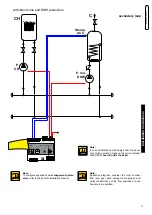
Connection diagram example:
2 modulex in pack managed by cascade manager
CH
C
P.
CH
P. Car.
DHW
Stemp.
ACC
Y4
1
2
3
4
1
2
3
1 2 3 4 5 6
Y3
Y2
12 11 10 9
8
7
6
5
4
3
2
1
0 1
2
3
4
5
6
7
8
9
9
8
10 11 12 13 14
2
1
3
4
5
6
7
Jp2
L
Y4
1
2
3
4
1
2
3
1 2 3 4 5 6
Y3
Y2
12 11 10 9
8
7
6
5
4
3
2
1
0 1
2
3
4
5
6
7
8
9
9
8
10 11 12 13 14
2
1
3
4
5
6
7
Jp2
SE
24 V - DC
CM 140 - cascade manager
24 V - DC
BR
BK
R
SMG
FL
D
230 V - 50 Hz
L1
PE
N
2
L1
PE
N
1
C
C
C
NC
NC
NO
1.3 (T.S.)
1.2 (P. min.)
1.1 (P. max.)
SAFE
1
NP
EL
1
Menu
L
N
S
S
M
Ext. Min
DP
In
0-10V
P.
mod.
D
230 V - 50 Hz
L1
PE
N
2
L1
PE
N
1
NP
EL
1
Menu
+ 24
V
(-)
e
B
U
S
+
1
2
3
4
1
2
3
4
5
6
7
Menu
6
7
8
9
10
11
12
F L
T A
INAIL
Y2 - BCM
1
2
3
4
5
1
Y3 - BCM
Y2-HSCP/UFLY
5
6
8
4
3
Y1 - BMM1
4
3
2
1
Y4 - BCM
2
3
e
B
U
S
-
e
B
U
S
+
FL
1
C
C
C
NC
NC
NO
1.3 (T.S.)
1.2 (P. min.)
1.1 (P. max.)
SAFE
L
N
S
S
M
Ext. Min
DP
In
0-10V
P.
mod.
6
7
8
9
10
11
12
F L
T A
INAIL
Y2 - BCM
1
2
3
4
5
1
Y3 - BCM
Y2-HSCP/UFLY
5
6
8
4
3
Y1 - BMM1
4
3
2
1
Y4 - BCM
2
3
e
B
U
S
-
e
B
U
S
+
B
B
0 1
2
3
4
5
6
7
8
9
0 1
2
3
4
5
6
7
8
9
primary loop
(*) Note:
for the cascade connection,
position the selector on the Bcm
in the indicated position.
(*) Note:
for the cascade connection,
position the selector on the Bcm
in the indicated position.
(*)
(*)


