


29
Installation instructions
ENGLISH
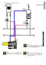
Connection diagram example:
Power supply, InAIl, modulating pump, external sensor, flow switch
D
230 V - 50 Hz
L1
PE
N
2
L1
PE
N
1
NP
EL
1
L
N
S
S
M
Ext. Min
DP
In
0-10V
P.
mod.
FL
1
C
C
C
NC
NC
NO
1.3 (T.S.)
1.2 (P. min.)
1.1 (P. max.)
SAFE
6
7
8
9
10
11
12
F L
T A
INAIL
Y2 - BCM
1
2
3
4
5
1
Y3 - BCM
Y2-HSCP/UFLY
5
6
8
4
3
Y1 - BMM1
4
3
2
1
Y4 - BCM
2
3
SE
Menu
B
KeY
no.
description
1
InAIl - Safety bodies
2
main electrical panel (not supplied)
B
Services connection return terminal board
d
Wieland mobile pow. supp. socket 230 V -
50hz
fl
Terminals for flow switch
Se
Terminals for external Sensor
SmG
Global flow sensor
P on_off
Manifold Pump Connections (on_off)
P mod
modulating pump connections


