


Technical f
eatur
es
11
BAHR’12 STD - EC - HP - HPEC - HPO - HPOEC
BAHR’ 12
Model
300
400
500
600
800
1000
1250
1500
1750
2000
2500
3000
4000
5000
6000
Ø
mm
219
219
219
219
258
258
308
308
358
358
408
408
458
488
488
Weight
empty
kg
1650
1650
2040
2040
2860
2860
3750
3750
4650
4650
6600
6600
9030
10590
11800
Weight in
oper.
kg
2175
2175
2800
2800
3940
3940
5305
5305
6655
6655
9490
9490
13185
16390
18560
T1
DN32
DN32
DN40
DN40
DN50
DN50
DN65
DN65
DN65
DN65
DN80
DN80
DN100
DN125
DN150
T2
DN40
DN40
DN40
DN40
DN40
DN40
DN40
DN40
DN40
DN40
DN40
DN40
DN40
DN50
DN50
T3
DN25
DN25
DN25
DN25
DN25
DN25
DN25
DN25
DN25
DN25
DN32
DN32
DN32
DN32
DN40
T4
DN25
DN25
DN25
DN25
DN25
DN25
DN25
DN25
DN40
DN40
DN40
DN40
DN40
DN40
DN40
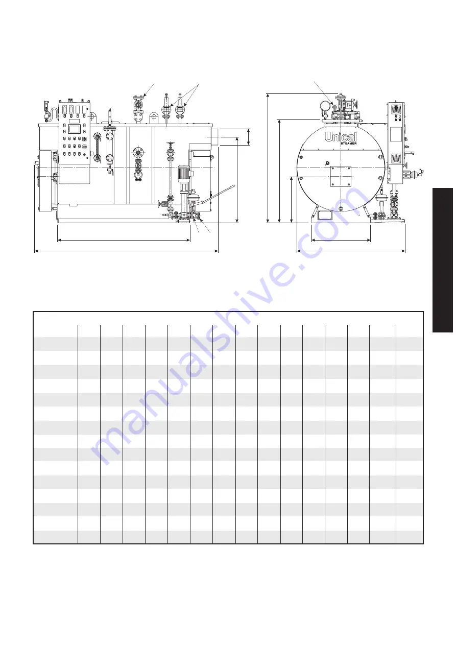
T1
Steam inlet
T2
Safety valve drain
T3
Water supply
T4
Boiler drain
B
Ø
T1
T4
L
C
D
E
H
A
W
T2
T3
T4
T3
T2
A
mm
780
780
860
860
950
950
1090
1090
200
1200
1470
1470
1700
1800
1850
W
mm
1474
1474
1861
1861
1996
1996
2126
2126
2246
2246
2296
2296
2756
2856
3026
B
mm
1550
1550
1750
1750
2120
2120
2526
2526
2750
2750
2830
2830
3300
3800
4003
L
mm
2340
2340
2565
2565
2950
2950
3414
3414
3543
3543
3860
3860
4360
4943
5236
D
mm
635
635
685
685
745
745
860
860
905
905
1080
1080
1170
1195
1210
E
mm
1333
1333
1453
1453
1593
1593
1783
1783
1918
1918
2243
2243
2473
2548
2618
H
mm
1820
1820
1940
1940
2077
2077
2294
2294
2422
2422
2774
2774
3031
3173
3315
C
mm
1167
1167
1266
1266
1349
1379
1555
1555
1685
1685
2004
2004
2187
2261
2326


