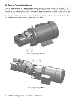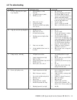
32 UNIBLOC-PD Operation & Service Manual: PD200-576
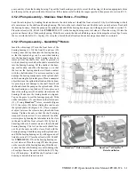
4.6 Relief Valve Cover Service
UNIBLOC
®
pumps may be supplied with a relief valve cover model #46, shown
in section 4.6.1 or model #B shown in section 4.6.2. Both models will minimize or
eliminate problems associated with over-pressurizing the pump. Although a com-
plete external relief system is recommended, the types illustrated are useful when
such systems are not practical.
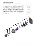
4.6.1 Relief Cover Model #46
This type functions only in one direction and must be oriented such that the high
pressure, or discharge side of the pump is always at the inlet of the relief valve.
The pressure is set in conjunction with a pressure gauge installed on the discharge
side of the pump. By compressing or decompressing the spring inside the valve, the
pressure at which the valve will open can be adjusted. This must be done while the
pump is operating at the desired flow rate. Extreme caution should be used to pre
-
vent damage to the pump or other equipment that is pressure sensitive. If the pump
is used to handle hot liquids, do not touch the pump or the valve without protection.
Unscrew the housing (10) to reveal the adjusting mechanism. Release the lock ring
(15) and turn it and the adjusting sleeve (16) clockwise until they bottom out. Turn
the sleeve counterclockwise until the pressure gauge begins to drop. Lock this posi-
tion with the lock ring (15). Keep in mind that this pressure must be approximately
0.3-0.7 bar (5-10 psig) lower than the desired relief pressure, since the pump will
continue to build pressure even though the valve may be open. Return the housing
(10) and tighten.
To service the valve seals the pump must not be oper-
ating, the system must be depressurized, and the pump
isolated from the remainder of the system. Remove the
housing (10) and mark the location of the lock ring
(15). Unscrew the adjusting sleeve (16) and remove
it. Remove the clamp (13) and separate the valve body
and the top containing the spring. Slide the piston, (18)
and (17), out and place its stem in a padded vise. Un-
screw the tip (17). O-rings (1), (2), and (3) may now
be replaced. Screw on the tip (17), roll o-ring (1) into
the groove and tighten. Lubricate o-ring (3) and slide
in the piston. Place the top with the piston in the valve
body (14) and secure with the clamp (13). Turn the
lock ring (15) so that it returns to the mark and thread
on the adjusting sleeve (16) tight against it. Replace
the housing (10) and tighten. The pump may now be
returned to service.
Summary of Contents for 54001010P20H6010T12E
Page 42: ...42 UNIBLOC PD Operation Service Manual PD200 576 UNIBLOC PUMP ...
Page 43: ...UNIBLOC PD Operation Service Manual PD200 576 43 UNIBLOC PUMP ...
Page 44: ...44 UNIBLOC PD Operation Service Manual PD200 576 UNIBLOC PUMP ...
Page 45: ...UNIBLOC PD Operation Service Manual PD200 576 45 UNIBLOC PUMP ...
Page 46: ...46 UNIBLOC PD Operation Service Manual PD200 576 UNIBLOC PUMP ...
Page 47: ...UNIBLOC PD Operation Service Manual PD200 576 47 UNIBLOC PUMP ...
Page 48: ...48 UNIBLOC PD Operation Service Manual PD200 576 UNIBLOC PUMP ...
Page 49: ...UNIBLOC PD Operation Service Manual PD200 576 49 UNIBLOC PUMP ...
Page 50: ...50 UNIBLOC PD Operation Service Manual PD200 576 3 ...
Page 51: ......
Page 52: ......

