background image

4


NOTE:


INTRODUCTION


Read  carefully  this  operation  manual  and  learn  about  the  design  and  operation  of  this 
fertiliser  distributor  and  its  components.  Strict  compliance  with  the  recommendations 
contained  in  this  operation  manual  shall  ensure  many  years  of  efficient,  trouble-free  and 
safe operation of the machine. In case of any problems and doubts related to the operation 

and  use  of  the machine,  please  contact  an  authorised  dealer or  the manufacturer’s  Sales 
Department.  The  Seller  is  required  to  specify  in  the  warranty  card  the  address  where 
warranty services are performed.


AGROMET  PILMET  spółka  z  ograniczoną  odpowiedzialnością  shall  be  grateful  for  any 
observations about this operation manual as well as comments about the fertiliser distributor 
and its use and operation.


AGROMET  PILMET  spółka  z  ograniczoną  odpowiedzialnością  shall  not  be  liable  for  any 
damage due to failure to comply with this operation manual.


Throughout the manual, the ‘left’ and ‘right’ sides of the fertiliser distributor are determined 
looking from the rear of the machine in the direction of its operation (travel).


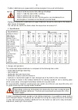
The  technical  safety  requirements  are  met  only  if  original  spare  parts  are  used  for  repair 
operations.


1.  HEALTH AND SAFETY PRINCIPLES


The majority of accidents that occur during work, operation or transport  are caused by failure 
to  observe  basic  health  and  safety  principles.  Therefore,  it  is  necessary  for  each  person 
handling the fertiliser distributor to strictly observe the following general work safety principles:


The fertiliser distributor can be operated and used only by appropriately qualified persons 
who have read this operation manual.


Before  using  the  fertiliser  distributor,  check  the  technical  condition  and  the  mounting  of 
particular  mechanisms  and  especially  the  elements  of  the  drive  system  and  working 
assemblies.


Do not use the machine which is not fully operational.


Tighten  all  loose  elements  and  immediately  replace  damaged  elements  with  the  new 
ones. 
In case of necessary repairs, use only original spare parts; the repair operations should 
be performed by appropriately qualified persons. 
All safety guards must be installed and undamaged.


Use protective clothing when operating the fertiliser distributor. 
Tractors used with the fertiliser distributor must have a cabin.


The machine can only be started in the operating position, having ensured that there are 
no people or animals within the distance of 50 metres.


The fertiliser distributor can only be operated at the nominal PTO speed of the tractor, i.e. 
540 rpm. Do not exceed 600 rpm.


In case of any failures, immediately turn off the drive transmitted from the tractor.


Use the type of shaft specified by the manufacturer in this operation manual. 
Do  not  operate  the  machine  with  a  damaged  (bent,  with  jamming  joints,  etc.)  or 
incomplete jointed-telescopic shaft.


The  fertiliser  distributor  should  be  used  with  a  tractor  in  the  class  specified  in  the 
technical specification of this operation manual.


Before work, make sure that the control elements are functioning properly.


Do not move the unit in the reverse gear with the working assembly drive turned on.


The fertiliser distributor must be coupled with a three-point linkage of the tractor prior to 
loading the fertiliser into the container.


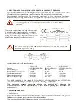
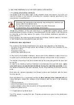
This operation manual, sold with the distributor, is to make the user familiar 
with the principles of correct operation and maintenance of the machine.


Summary of Contents for MX

Page 1: ...ul Fabryczna 2 Phone 48 77 444 45 86 Fax 48 77 416 20 83 www uniamachines pl SUSPENDED FERTILISER DISTRIBUTOR MX MXpremium and MS USER S GUIDE AND OPERATION MANUAL SPARE PARTS CATALOGUE Imported and d...

Page 2: ...Please read this operation manual before your start the machine and observe the safety instructions provided herein...

Page 3: ......

Page 4: ...1 Brzeg ul Fabryczna 2 Opole Province Phone 48 77 444 45 86 Maintenance and repairs 48 77 444 45 11 Fax 48 77 416 20 83 SUSPENDED FERTILISER DISTRIBUTOR MX MXpremium and MS USER S GUIDE AND OPERATION...

Page 5: ...he distribution data table The provided machine settings pertaining to the crosswise distribution apply in consequence to the weight distribution and not nutrient distribution this applies particularl...

Page 6: ...on 4 Operation and use 5 Machine operation 6 Maintenance 7 Features and accessories 8 Disassembly and scrapping 9 Adjustment and repairs of the most important fertiliser distributor elements II MACHIN...

Page 7: ...who have read this operation manual Before using the fertiliser distributor check the technical condition and the mounting of particular mechanisms and especially the elements of the drive system and...

Page 8: ...butor its steerability and braking capacity must be maintained Make sure that the hydraulic elements are not pressurised when connecting hydraulic pipes of the tractor Check the position of the levers...

Page 9: ...tractor or be wearing hearing protectors During the operation of the fertiliser distributor there are no risks caused by vibrations because the operator stays in the cabin of the tractor with a cushio...

Page 10: ...190 Meaning Never touch the elements that can crush your limbs such as dosing valve or screen elements as long as the parts located there can be still in motion K 258 Meaning Danger due to ejected fe...

Page 11: ...purchased fertiliser distributor has not been damaged during transport to the customer as well as whether the machine has been fully equipped in accordance with the order You can claim compensation o...

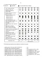
Page 12: ...302 250 Nm 22 kW 765 mm 890 mm 560 mm 4R 302 4 BA 302 250 Nm 22 kW 990 mm 1 185 mm 710 mm 5R 502 7 BA J501 400 Nm 35 kW 1 430 mm 1 755 mm 1 010 mm The shaft marked with the codes 4R 302 2 BA 302 4R 3...

Page 13: ...198 215 265 290 350 615 625 635 3 Design and operation The suspended fertiliser distributor is composed of the following basic units frame with the linkage assembly load container distribution disc an...

Page 14: ...the fertiliser distributor is powered by the external hydraulics of the tractor and is designed to open by means of hydraulic cylinders the holes used to dose the fertiliser to distribution discs dur...

Page 15: ...s resulting from the fertiliser distributor s working width Fig 2 and the overlap of the distribution zones When opening and closing the distribution slot at the edges of the field allow for the reach...

Page 16: ...plates Check the chain of the chain transmission and lubricate Refill grease in all greasing points Check the pivot connections and grease Lubrication All greasing points should be filled with grease...

Page 17: ...tribution disc control and power both discs together mechanical KR 1 signalling device with operation manual Removable transport wheels MACHINE TYPE Ms 850 1200 1600 2100 2500 3000 Mx premium The foll...

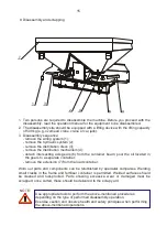
Page 18: ...axis gears 6 from the container beam pour the oil located in the gears to a separate container remove the extension 7 from the load container Worn out parts and components can be refurbished by speci...

Page 19: ...t the hydraulic connections of the tractor 40 l min NOTE Adjust reset the distribution mechanisms in the following manner Insert a 12 bar 1 in the outlet opening as shown in the figure Use the complet...

Page 20: ...e distribution discs there is a movable lever connected with the adjustment damper at the bottom of the container The degree of opening of the slot is determined by the scale along which the lever can...

Page 21: ...the machine should be suspended at the height of 90 90 from the field s surface In the case of higher crop suspend the machine in line with the data for top dressing For very dense fields e g rape su...

Page 22: ...the lever setting for working speeds not included in the distribution data table Example Fertiliser Working width Estimated working speed Dose Calcium ammonium nitrate 27 5 ZA K dzierzyn 12 m 6 km h 4...

Page 23: ...h up to 23 m factor 40 Measurement distance for a given work width 500 working width m Working width above 24 m factor 20 Measurement distance for a given work width 3 1 2 By taking measurement at a h...

Page 24: ...value we increase the working width Short blades cover the internal range of the working width whereas the long ones the external range For certain product line e g calcium ammonium nitrate it is pos...

Page 25: ...fferent working widths Disc rotation direction right disc Fig 3 In order to achieve different working width values the distance between the paths the blades are gradually repositioned in the openings...

Page 26: ...e Fig 5 2 and set the long blade Fig 5 3 in the hole A3 of the scale Fig 5 4 and screw in the wing nuts Fig 4 5 6 Control of the set working width by means of portable measuring vessels The actual set...

Page 27: ...er to achieve optimum distribution have been presented on page 25 Such operations are intended to check the regularity of distribution of the fertilisers which are not included in the distribution dat...

Page 28: ...her value Perform the adjustment on the left disc too 5 4 3 2 1 Disc rotation direction Example 4 Uneven distribution Fertiliser dose exceeded only between the paths Right disc Disc rotation direction...

Page 29: ...ith bolt 4 Screw in the clamping screw 2 into the gear shaft hole to prevent the threaded hole from being covered with fertiliser Hang the control container 5 bucket on hook 6 Continued in sections 4...

Page 30: ...he specified period of time as specified on p 20 Weigh the obtained fertiliser dose in the container bucket and multiply by the factor amounting to 40 which corresponds to the dose per hectare Example...

Page 31: ...ng blade L 280 No 2053 03 004 0 and 2053 03 006 0 B short blade L 215 No 2053 03 003 0 and 2053 03 005 0 left right Scale range from V to 6 Disc diameter 480 mm A 6 5 4 3 2 1 0 V LM V 0 1 2 3 4 5 6 B...

Page 32: ...B4 A4 B4 A4 B4 A4 CAN 27 5 N gran 3 87 mm b d 0 92 kg l Zak ady Azotowe W oc awek B4 A4 B4 A4 B4 A4 B4 A4 Polidap NP 18 46 gran 3 36 mm b d 0 84 Zak ady Azotowe Police B2 A3 B3 A3 B3 A3 B3 A3 Amofoska...

Page 33: ...ng blade L 360 No 2053 03 008 0 and 2053 03 010 0 B short blade L 260 No 2053 03 007 0 and 2053 03 009 0 left right Scale range from V to 6 Disc diameter 480 mm A 6 5 4 3 2 1 0 V LM V 0 1 2 3 4 5 6 B...

Page 34: ...b d 0 92 kg l Zak ady Azotowe W oc awek B2 A3 B2 A3 B2 A3 B3 A3 Polidap NP 18 46 gran 3 36 mm b d 0 84 Zak ady Azotowe Police B2 A1 B2 A2 B2 A2 B3 A2 Amofoska NPK 4 16 18 granul 3 27 mm b d 1 05 Fosf...

Page 35: ...1 V 0 1 2 0 3 4 5 6 A B 6 V 5 0 4 1 3 2 2 3 0 V 4 5 6 B LM 30 DISCS A long blade L 410 No 2053 03 012 0 and 2053 03 014 0 B short blade L 300 No 2053 03 011 0 and 2053 03 013 0 left right Scale range...

Page 36: ...mm b d 0 92 kg l Zak ady Azotowe W oc awek B1 A2 B2 A2 B2 A2 B2 A2 B3 A3 Polidap NP 18 46 gran 3 36 mm b d 0 84 Zak ady Azotowe Police B1 A1 B2 A2 B2 A2 B2 A3 B2 A5 Amofoska NPK 4 16 18 granul 3 27 mm...

Page 37: ...A3 B4 A3 B4 A4 53 White lupin b d 0 76 B4 A2 B4 A3 B4 A3 B5 A4 53 Winter vetch b d 0 83 B3 A4 B3 A4 B4 A5 B4 A5 B4 A5 54 Sunflower b d 0 44 cleaned B1 A4 B1 A4 B3 A4 B3 A4 B3 A5 54 Rape b d 0 7 B2 A3...

Page 38: ...8 5 7 1 8 5 6 8 5 7 8 0 6 4 5 3 7 1 5 7 4 7 10 16 3 13 0 10 8 13 6 10 8 9 0 10 8 8 7 7 2 10 2 8 1 6 8 9 0 7 2 6 0 When loading the fertiliser distributor avoid breathing dust and direct skin contact w...

Page 39: ...in the blade position in a disc hole changing to a higher value on the scale increases the distribution width the fertiliser range raised b change in the blade length increasing the blade length incre...

Page 40: ...r of positions on the scale 5 to 6 2 7 to 9 3 10 to 11 4 12 to 14 5 15 to 18 6 LM LM LM TL TL B A 1 2 1 2 3 4 5 5 4 3 2 3 4 5 5 4 3 1 2 1 I Left telescopic blade set TL 10 L 120 170 No 2039 93 004 0 T...

Page 41: ...A2 14 0 A2 14 0 A2 150 A3 180 A3 20 0 A4 230 A2 310 A2 310 Urea granulated B L mm A L mm B3 x 120 B3 x 120 B4 12 0 B4 120 B2 180 B2 190 B2 240 B3 250 A1 x 120 A1 x 140 A1 14 0 A1 140 A4 180 A4 19 0 A...

Page 42: ...of the disc Set blade A Fig 6 item 2 in hole 4 on the scale Fig 6 item 3 and blade B Fig 6 item 4 in hole 2 on the scale Fig 6 item 5 and tighten the wing nuts Changing the blade setting to a higher v...

Page 43: ...40 5 4 2 3 1 Fig 6 Fig 7...

Page 44: ...20 g 5 50 0 1 18 8 g g 1 10 0 m m 5 5 m m 0 0 m m 5 5 m m 1 10 0 m m 1 15 5 m m 2 20 0 m m 2 25 5 m m LM LM LM TL TL B A 1 2 1 2 3 4 5 5 4 3 2 3 4 5 5 4 3 1 2 1 I Left telescopic blade set TL 10 L 12...

Page 45: ...230 B2 290 B2 300 A3 130 A3 130 A3 220 A3 220 A4 230 A4 310 A5 310 Urea prilled B L mm A L mm B4 120 B4 120 B2 200 B2 210 B2 230 B1 290 A1 140 A3 140 A5 200 A5 210 A5 230 A4 290 Ammonium phosphate B...

Page 46: ...o the right After driving around the field replace the TL border disc with the LM distribution disc again Centrifugal distributors also spread the fertiliser backwards therefore in order to distribute...

Page 47: ...44 T 1 T 2 T 3 T 1 T 2 T 3 P 1 P 2...

Page 48: ...92 660 792 633 528 660 528 440 594 475 396 54 1239 991 826 1032 826 688 661 661 551 688 551 459 619 495 413 55 1290 1032 860 1075 860 716 688 688 573 716 573 478 645 516 430 56 1340 1072 893 1117 893...

Page 49: ...640 512 427 576 461 384 52 1260 965 804 1005 804 670 804 643 536 670 536 447 603 482 402 53 1314 1008 840 1050 840 700 840 672 560 700 560 467 630 504 420 54 1390 1051 876 1095 876 730 876 701 584 730...

Page 50: ...2 318 430 334 287 46 912 730 608 760 608 507 608 487 405 507 405 338 456 365 304 47 965 772 644 804 644 536 644 515 429 536 429 358 483 386 322 48 1019 815 679 849 679 566 679 544 453 566 453 377 510...

Page 51: ...698 582 698 559 466 582 466 388 524 419 349 48 1106 8885 737 922 737 614 737 590 492 614 492 410 553 442 369 49 1165 932 777 971 777 647 777 621 518 647 518 432 583 466 388 50 1225 980 817 1021 817 68...

Page 52: ...463 370 308 45 984 787 656 820 656 547 656 525 437 547 437 365 492 394 328 46 1044 835 696 870 696 580 696 557 464 580 464 387 522 418 348 47 1105 884 737 921 737 614 737 589 491 614 491 409 552 442...

Page 53: ...494 412 556 445 370 46 1179 998 786 982 786 655 786 629 524 655 524 437 589 472 393 47 1247 1054 832 1039 832 693 832 665 554 693 554 462 624 499 416 48 1317 1110 878 1097 878 732 878 702 585 732 585...

Page 54: ...183 153 40 454 363 303 378 302 252 303 242 202 284 227 189 252 202 168 Wheat undressed 0 78 kg l Lever position m 10 12 15 16 18 8 km h 10 12 8 km h 10 12 8 km h 10 12 8 km h 10 12 8 km h 10 12 27 225...

Page 55: ...7 303 242 202 36 585 468 390 488 390 325 390 312 260 366 292 244 325 260 217 37 630 504 420 525 420 350 420 336 280 394 315 263 350 280 233 Oat undressed 0 48 kg l Lever position m 10 12 15 16 18 8 km...

Page 56: ...41 340 272 227 272 218 182 255 204 170 227 182 151 42 361 289 241 289 231 193 271 217 181 241 193 160 White lupin 0 76 kg l Lever position m 12 14 16 18 20 8 km h 10 12 8 km h 10 12 8 km h 10 12 8 km...

Page 57: ...2 206 165 138 194 155 129 172 138 115 29 344 275 229 286 229 191 229 183 153 215 172 143 191 153 127 30 379 304 253 316 253 211 253 202 169 237 190 158 211 169 141 31 417 334 278 348 278 232 278 223 1...

Page 58: ...5 19 6 16 3 23 0 18 4 15 3 14 72 5 58 0 48 3 54 4 43 5 36 3 36 3 29 0 24 2 29 0 23 2 19 3 27 2 21 8 18 1 15 85 0 68 0 56 7 63 8 51 0 42 5 42 5 34 0 28 3 34 0 27 2 22 7 31 9 25 5 21 3 16 100 80 0 66 7...

Page 59: ...2 73 3 58 6 48 9 55 0 44 0 36 6 48 9 39 1 32 6 44 0 35 2 29 3 36 6 29 3 24 4 13 86 6 69 2 57 7 64 9 51 9 43 3 57 7 46 2 38 5 51 9 41 5 34 6 43 3 34 6 28 9 14 101 81 0 67 5 75 9 60 7 50 6 67 5 54 0 45...

Page 60: ...h 10 12 8 km h 10 12 8 km h 10 12 8 km h 10 12 8 km h 10 12 6 10 7 8 6 7 1 8 0 6 4 5 4 7 1 5 7 4 8 6 4 5 1 4 3 7 17 2 13 8 11 5 12 9 10 3 8 6 11 5 9 2 7 7 10 3 8 3 6 9 8 24 7 19 7 16 4 18 5 14 8 12 3...

Page 61: ...8 3 23 6 31 4 25 2 21 0 28 3 22 6 18 9 14 55 1 44 1 36 8 41 4 33 1 27 6 36 8 29 4 24 5 33 1 26 5 22 1 Ryegrass 0 51 kg l Lever position m 10 12 15 16 18 8 km h 10 12 8 km h 10 12 8 km h 10 12 8 km h 1...

Page 62: ...llary items or non genuine attachments to the machine or the modification of the machine in anyway may render the machine less safe and that advice of the Dealer should be obtained prior to such chang...

Reviews: