11
5
6
4
3
2
Distribution disc and mixer drive
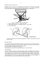
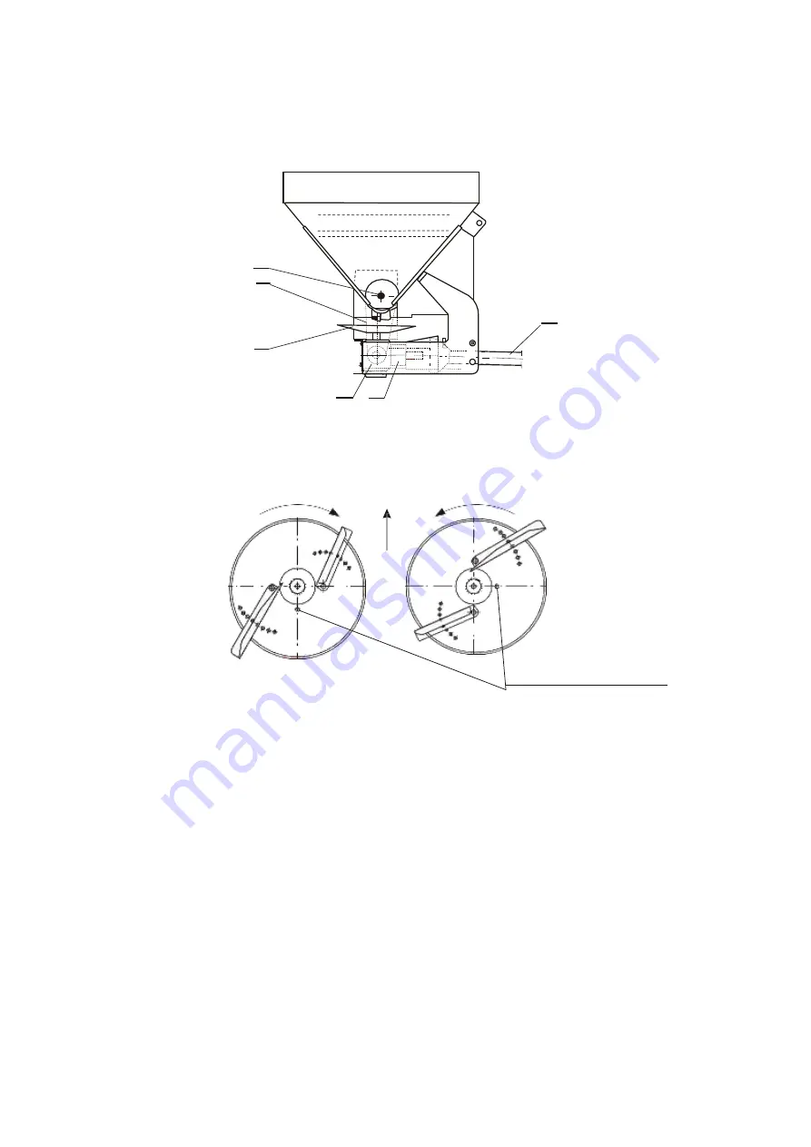
Distribution discs 4 (Fig. 1) are powered by the tractor’s PTO through the jointed-
telescopic shaft 1, bevel gear 2 and intersecting axis gears 3. The power is transmitted
to the mixer shaft 5 from the bevel gear 2 by means of chain transmission 6.
1
Fig. 1 Distribution disc and mixer drive
1
– jointed-telescopic shaft; 2 – central bevel gear;
3
– intersecting axis gear; 4 – distribution disc; 5 – mixer shaft;
6
– chain transmission
LM
Left
Right
A
B
Locating opening
Location of the blades on the right-hand side disc in relation to the blades on the left-
hand side disc.
Hydraulic system
The hydraulic system of the fertiliser distributor is powered by the external hydraulics of
the tractor and is designed to open, by means of hydraulic cylinders, the holes used to
dose the fertiliser to distribution discs during operation.
The dosing holes are closed by pull springs.
The dosing holes can also be opened and closed by mechanical links.
Load container
The load container is made of truncated pyramid shaped metal plate and is attached to
the frame. An extension that increases the loading capacity is attached to the container.
In the upper part of the container there are brackets to fasten portable wiring system.
The portable wiring system can be purchased at the factory when purchasing the
fertiliser distributor. You can also install a portable wiring system from other machine. A
load container protective cover (special option) is also available.
LM
B
Summary of Contents for MX
Page 3: ......
Page 43: ...40 5 4 2 3 1 Fig 6 Fig 7...


