12 UTG2000B Series
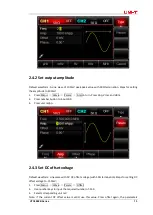
Description:
●
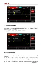
CH1/CH2: the selected channel will be highlighted.
1) Limit indicates output range is at limit. White color: valid; Grey color: invalid.
2)
50Ω
indicates the matched impedance of output terminal
(1Ω
to 10K
Ω
adjustable, or high
resistance; default:50
Ω)
3)
:
sine wave. Different modes have different menu.
●
Bezel menu on the right: corresponding buttons for different function. Highlighted display
indicates that the function is selected.
●
Bezel menu on the bottom: sub menu belonging to the right menu. Highlighted display indicates
that the function is selected.
If the submenu has over 6 labels, use button to flip over.
1) Labels on the right of screen: Highlighted display indicates that the label is selected. If not,
press corresponding soft key to select.
2) Labels at the bottom of screen: Sub label belongs to the next category of Type label. Press
corresponding button to select sub labels.
2.4 Basic Waveform Output
This chapter introduces how to output different waveforms. Default waveform: sine wave with 1
kHz and 100mVpp.
2.4.1 Set output frequency
Default waveform: A sine wave of 1 kHz frequency and 100mV amplitude (with
50Ω
termination).
Steps for setting the frequency to 2.5MHz:
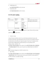
1) Press Menu
→
Wave
→
Param
→
Freq in turn to set the frequency. Pressing Freq to
edit frequency or period.
2) Press the number keyboard to input 2.5.
3) Select corresponding unit on the bottom bezel menu: MHz
Summary of Contents for UTG2122B
Page 2: ......
Page 129: ...UTG2000B Series 127 This user manual may be revised without prior notice...
Page 130: ...128 UTG2000B Series...


