V.
External Structure
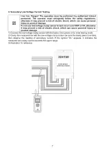
1. Primary clamp sensor
2. Antenna
3. Power indicator
4. Power button
5. Connector of insulation stick
6. LCD display
7. MEN button and arrow buttons
8. Input port for secondary clamp sensor
9. USB port
10. Output plug for secondary clamp sensor
11. Secondary clamp sensor
12. Insulation stick
VI.
Operating Instructions
Please check if any product component is damaged before use. Do
not use if damaged component is found.
Install battery according to the user manual.
1. Power On/Off the Primary High-Voltage Clamp Sensor
When “
” is pressed, the
high-voltage clamp sensor is powered on (with the indicator light “
” lit
up) and it starts automatic testing. The testing results (current, pulse and others of the high-voltage
end) are sent to the tester via wireless transmission. The indicator light “
” flashes continuously
15 minutes after the clamp sensor is powered on, to indicate auto power off. After the indicator light
“
” flashes continuously for about 30 seconds, the clamp sensor powers off automatically to save
battery power. If “
” is pressed when the POWER indicator light flashes continuously, the clamp
sensor can continue working. Press “
” to power off the clamp sensor.
2. Power On/Off the Tester
When “
” is pressed, the tester powers on and then enters receiving mode (picture below). The
primary current is the testing data of the high-voltage end, the secondary current is the testing data
4


