background image

The monitor software can indicate maximum, minimum and average values, and have multiple 
functions including dynamic display, real-time monitoring, alarming threshold setting, alarming 
indication, data viewing/saving/printing, etc. 
 

UT225B

  has the same functions as High/Low Clamp Meter, Aerial Current Tester, and other 

products. 


III.

 Electrical Symbols 


Extremely dangerous! The operator must follow the safety information strictly, 

otherwise it may present a risk of electric shock, which can cause personal 

injury or death. 


Danger! The operator must follow the safety information strictly, otherwise it 

may present a risk of electric shock, which can cause personal injury or death. 


Warning! The operator must follow the safety information strictly, otherwise it 

can cause personal injury or product damage. 

  Alternating Current (AC) 


Direct Current (DC) 


IV.

 Technical Specifications 

1. Basic conditions: 

Influence quantity 

Basic conditions  Work conditions 

Remark 

Ambient temperature 

23°C±5°C 

-15°C±50°C 


Ambient humidity 

40%~60% 

70% 


Distortion rate of sinusoidal wave 

1% 

3% 


Signal frequency 

50Hz±5Hz 

45Hz±65Hz 


External electric and magnetic 

fields 

Shall be avoided 

Location of measured conductor 

Place the measured conductor at the center of the 

clamp jaws. 


2. Technical parameters: 

Functions 

Testing on current and turns ratio of high/low-voltage current 

transformer and transformer primary/secondary circuit; 

identification of polarity and phase type. 

Power supply 

DC6V LR03 alkaline dry batteries (1.5V AAA × 4), with the ability 

to work for 30 hours continuously. 

Testing mode 

By clamp sensor (CT) 

Testing accuracy of 

primary current 

Range: 0.0A~800A 

Resolution: 0.1A 

Accuracy: ±0.5%FS 

Testing accuracy of 

secondary current 

Range: 0.00mA~5A 

Resolution: 0.01mA 

Accuracy: ±0.5%FS 

Measurement range of 

turns ratio 

1~500 

Resolution of turns ratio 

0.1 

Dimensions of primary 

clamp sensor 

Clamp jaws size:   48mm 

External dimensions: 76mm × 255mm × 31mm 

Dimensions of secondary 

transformer 

Clamp jaws size:   8mm 

External dimensions: 137mm × 40mm × 19.5mm 

2

Summary of Contents for UT225B

Page 1: ...UT225B UT225B P N 110401111909X UT225B High Voltage Transformer Turns Ratio Tester...

Page 2: ...s 4 1 Power On Off the Primary High Voltage Clamp Sensor 2 2 Power On Off the Tester 2 3 Testing of High Voltage Current and Overhead Current 2 4 Secondary Low Voltage Current Testing 2 5 Testing of T...

Page 3: ...to the instruction It is recommended to perform dielectric test on the product once a year at least AC 60kV rms between both ends 5 pieces of connected insulation sticks II Introduction UT225B High Vo...

Page 4: ...ty Basic conditions Work conditions Remark Ambient temperature 23 C 5 C 15 C 50 C Ambient humidity 40 60 70 Distortion rate of sinusoidal wave 1 3 Signal frequency 50Hz 5Hz 45Hz 65Hz External electric...

Page 5: ...r than 4 8V the symbol appears to indicate replacing battery Transmission distance of primary clamp sensor 100M wireless transmission Data transfer USB Connecting wire of secondary clamp sensor 2M Dis...

Page 6: ...with the indicator light lit up and it starts automatic testing The testing results current pulse and others of the high voltage end are sent to the tester via wireless transmission The indicator lig...

Page 7: ...ise it may present a risk of electric shock which can cause personal injury or death The insulation stick must be connected when performing testing by clamping high voltage line otherwise it may prese...

Page 8: ...or primary current If the tester displays OL for primary current it indicates the measured primary current is over the upper range specified by the high voltage clamp sensor To remove the high voltage...

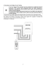
Page 9: ...e clamp sensor to test circuit over 600V or 5A otherwise it may present a risk of electric shock which can cause personal injury or product damage 1 Connect the low voltage clamp sensor with the teste...

Page 10: ...150 5 150 150 100 0 3...

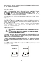
Page 11: ...by the nameplate at the current transformer If the actual test error is over the set error the symbol OL appears on bottom right of the LCD On site wire connection 6 Data Hold Storage When is pressed...

Page 12: ...or software can indicate maximum minimum and average values and have multiple functions including dynamic display real time monitoring alarming threshold setting alarming indication data viewing savin...

Page 13: ...rying bag 1 pc AAA alkaline dry battery 8 pc User manual 1 pc The content of this user manual cannot be used as a reason for using the product for special purposes The company is not responsible for o...

Reviews: