43
Adjust the vertical SCALE knob to change the amplitude of each channel,
and adjust the horizontal SCALE knob to change the time base to get a better
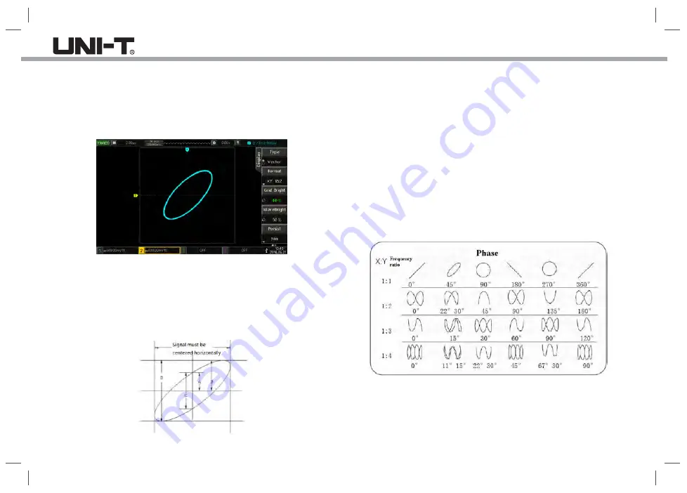
display effect of the Lissajous figures. The waveform in XY mode is shown
in the following figure:
Picture 7-1 Waveform display in XY mode
8.3 Application of XY Mode
The Lissajous method makes it easy to observe the phase difference between
two signals
of the same frequency. The following figure shows the observation of phase
difference.
According to sinθ = A/B or C/D, θ is the phase difference angle between
channels, and the definition of A, B and C, D are shown above, it can be
calculated that the phase difference angle θ = ± arcsin (A/B) or θ = ± arcsin
(C/D). If the main axis of the ellipse is in the quadrants I, III, then the
calculated phase difference angle should be in the quadrants I, IV, i.e. within
(0~π/2) or (3π/2~2π); If the main axis of the ellipse is in the quadrants II,
IV, then the calculated phase difference angle should be within (π/2~π)
or (π~3π/2).
In addition, if the frequency or phase difference of the two detected signals
is an integer, the frequency and the phase relationship between the two
signals can be calculated according to the pattern in the following chart:


