8
/
14
3.2 Before Use
To perform a quick verification of the instrument’s normal operations, please follow the steps below
:
(1) Connect to the Power Supply
The power supply voltage range is from 100 VAC to 240 VAC, the frequency range is 45 Hz to 440 Hz.
Connect the oscilloscope to the power supply line that came with the oscilloscope or any power supply
line that meets the local country standards. Turn on the power button, which on the back of the
oscilloscope. The soft power button
in the front of the oscilloscope should be on red.
(2) Boot Check
Press the soft power button
and the light should change to green. The oscilloscope will show a boot
animation, and then enter the normal interface.
(3) Connect Probe
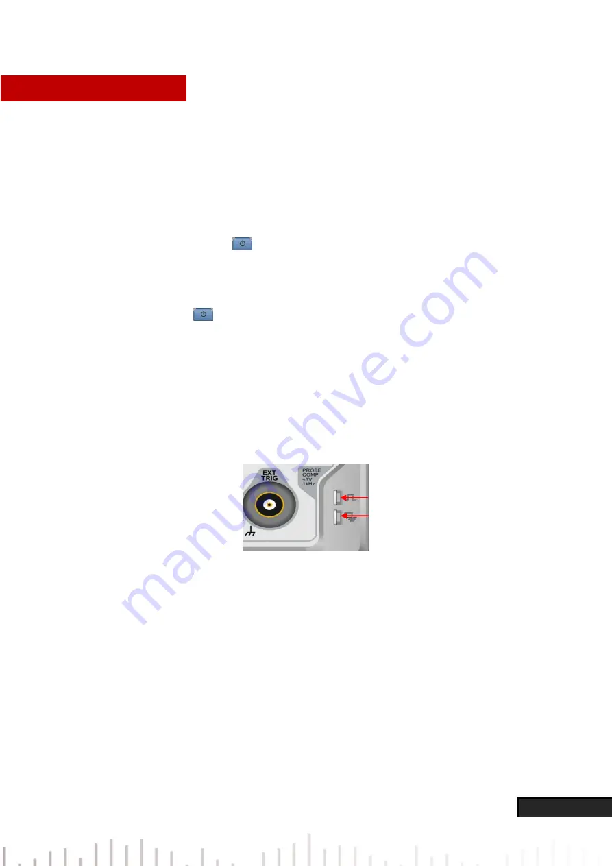
Use probe in the attachment and connect it BNC terminal to the channel 1 BNC terminal of the
oscilloscope. Connect the probe’s main alligator clip to the “Compensating signal terminal” and the ground
clip is connected to the “Ground terminal” shown below. The output of the compensating signal should
be a 3 Vpp amplitude, default frequency is 1 kHz.
Figure 1 Compensating Signal and Ground Terminal
(4) Function Check
Press the AUTO key, a 3 Vpp 1 kHz square ware should appear. Repeat step 3 for all channels.
(5) Probe Compensation
When the probe is connected to any input channel for the first time, this step might be required in order
to match the probe and the input channel. Probes that are not compensated may lead to measurement
errors or mistake. Please follow the following steps:
Compensating signal terminal
Ground
terminal


