


Bi-spectrum network camera
Configuring Thermal
User Manual
34
Issue V1.0
(
2021-10-25
)
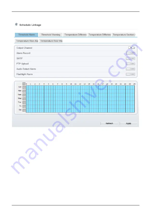
Figure 3-8
Schedule Linkage
Step 2
Tick the output channel. Enable alarm record, SMTP, FTP upload, audio alarm, and
flashlight alarm. The audio alarm file will be set at
Alarm > Sound Alarm Outpu
t
interface, as shown in Figure 3-9.


