Umirs Europe Ltd. Predix
- 9 -
PRELIMINARY SET-UP
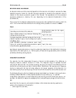
The detector has two systems for the determination of proper threshold levels: “automatic” and
“manual”. In the automatic system, the processor determines the optimal threshold levels for the
detection of intruders penetrating the detection zone on a ground surface. In the manual system,
the optimal threshold levels are explicitly specified by the operator. As a rule, the need for manual
adjustment arises in the event of a significant operational variation from the routine operating
conditions specified in this manual.
It should be noted that, in the automatic system, the optimal threshold levels are determined in
distribution box in relation to the average strength of the radio signal received. The detector
automatically adapts to gradual changes in the received radio signal’s average strength resulting
from slow changes in weather conditions.
ATTENTION!
To increase the noise proof feature of thedetector, it is necessary to establish the
highest possible absolute value for the operating threshold.
Switch on the supply of the detector and check it’s voltage at the corresponding outputs of the units.
The voltage can be checked by any measuring device that provides such measuring. The value
measured, taking into account the required reserve for usage must be between 12-36 V. After the
power supply is switched on, it is necessary to perform the adjustment of the detector.
Attention! In the settings schemes the detector generates signal about the malfunction (output
circuit is disconnected)
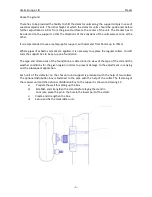
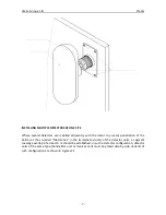
To adjust the detector, loosen the fixing nuts of the transmitter unit and receiver unit units. To
reach the maximal indication of the signal level, turn consecutively the transmitter unit and the
receiver unit slowly and gradually, inspecting visually the direction of the emissions of the units.
Comments:
1 In certain cases where the level of the received signal is insufficient (basically where the
length of the section is close to the maximum), it is recommended to change sequentially the
height of the settings of the transmitter unit and (or) receiver unit in the range 0.9-1 m with 1
cm) steps with the subsequent adjustment of units (cm higher).
2 It must be taken into account that, in certain cases, the maximum level of the received
signal during adjustment is achieved when the detector units have been inadvertently oriented
in the direction of a nearby reflective surface (e.g., metal fencing, water surface, etc.). In such
cases it is not advised to orient the detector units in such a direction.
а)
Upon the finishing of the adjustment, the fixing nuts of the units have to be
tightened, not allowing to change the position (controlling the level of the signal received).
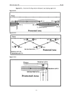
b) One of the causes of frequent false responses of the detector may be the impact on
the receiver unit of the emission of the transmitter unit of the neighbouring sections. Such impacts
can be detected by switching off the power supply of the neighbouring transmitters. In detecting
the impacts it is necessary to change the frequency band of the detector. The change of the
frequency band is performed simultaneously in the receiver unit and the transmitter unit
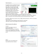
with the
adjustment software.


