34
YK18-0012-AI-101-02
4
.
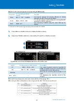
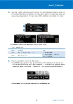
Select the function corresponding to the output of the connected device from etc.1 and etc.2 in
P1 and P2 of the Menu screen.Check the instruction manual of the connected device and
prepare the wiring suitable for the input / output of this unit.Refer to section 2.4.8 for details.
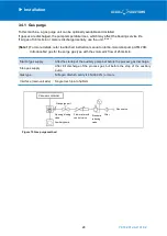
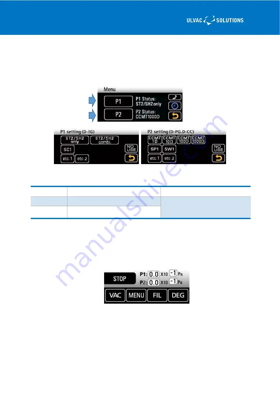
Figure20 Menu screen and G-TRAN models on the P1 and P2 screen.
etc.1 / etc.2 functions
Switch
Function
Work
etc.1
P = a × 10 ^ (( V – b )/ c + d )
P
:
Display Value
V
:
Input Voltage
DC0-10V
A,b,c,d
:
variable
etc.2
P = ( V / a ) × b
5
.
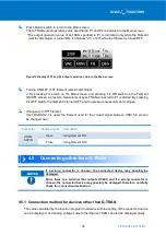
Press Return switch to return to the Main screen.
The G-TRAN output operation value specified in P1 and P2 is indicated in the Main screen.
*The output operation value of G-TRAN specified in P1 is indicated only while the filament
(electric discharge) is turned ON. It indicates "0.0 x 100" while the filament is turned OFF.
Figure21 Display of P1 and P2 output operation value on the Main screen


