background image


4-2

Edition October 1996


The Ultre 5400 imagesetter requires photo material sensitive in the 670 nano-
meter range (visible-red). Some of the suitable materials are identified in a list
of tested materials available from Ultre.


The maximum capacity of the Bulk Load Supply Cassette is 250 feet (75
meters) for material thickness of 4.5 mil.


Preparing the Bulk Load Supply Cassette 
(Daylight Load)


(Ref: Figures 1-4)


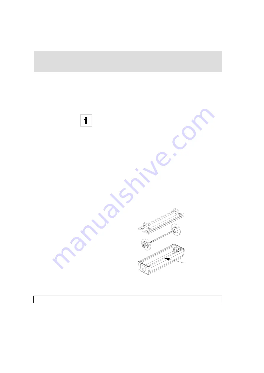
1. Place the supply cassette on a table with the material exit slot facing you.

Loosen the four quarter-turn fasteners counterclockwise and lift off the cassette
lid. (Ref:Fig.1)

Cassette lid with
quarter-turn fasteners

Spool assembly with
end bells and brake

Material exit slot

Fig.1

Summary of Contents for 5400

Page 1: ...Ultre 5400 User Manual ULTRE a division in the Heidelberg group This document was created with FrameMaker 4 0 4 ...

Page 2: ...uring training courses The contents of this documentation are correct at the time of going to press The information contained in this manual about performance and speed as well as technical data concerning application of our products is not legally binding as it does not constitute a written contract of features We point out that companies trademarks and product names mentioned in this manual fall...

Page 3: ...ntroduction 2 1 Product Description 2 2 Installation 2 3 3 Control Panel 3 1 Push Button Controls 3 3 LCD 3 6 LED 3 9 Machine Operation 3 10 4 Loading 4 1 Preparing the Bulk Load Supply Cassette 4 2 Loading Photo Material 4 8 Using Paper Photo Materials 4 18 5 Changing Default Settings 5 1 Menus and Functions 5 3 Density 5 4 LCD Adjustments 5 5 Set Power On Resolution 5 6 Before You Start This doc...

Page 4: ...Film Advance Length 5 8 Buffer Mode 5 9 Program Revision 5 9 Reverse Feed 5 10 Punch Distance 5 10 Auto Punch 5 11 Auto Advance 5 12 Auto FA Length 5 12 Print Test 5 13 6 Messages 6 1 LCD Status Messages 6 2 Error Messages and Corrective Procedures 6 4 Control Program Upgrade Procedures 6 10 7 Technical Data 7 1 ...

Page 5: ...le for use in the Ultre 5400 imagesetters Notes on this Documentation This documentation contains Notes on Technical Safety Introduction with Installation Control Panel Description of control panel push button controls and LCD display and machine operation Loading Photographic Material including preparing the bulk load supply cassette Change Default Settings Messages Status and error messages incl...

Page 6: ...tion The text contains information which must be observed in order to protect the user from danger This information must be observed to protect the equipment the software and the data from being damaged The text contains general or additional information about a certain subject ...

Page 7: ...andards and Regulations 1 4 Service 1 4 Position of Laser Safety Labels 1 6 Radio Interference 1 7 Notes for Users in the US 1 7 Notes for Users in Canada 1 7 Safety Standards 1 8 Electrical Safety 1 9 Mechanical Safety 1 9 General Safety 1 9 Electromagnetic Compatibility 1 9 Approvals 1 10 This document was created with FrameMaker 4 0 4 ...

Page 8: ...not place any objects or liquids on the unit Ventilation outlets must be kept clear at all times General Information Pay attention to the notes on ambient conditions in Chapter 7 Technical Data and to the conditions for installing the unit in Chapter 2 Introduction section Installation Unit connectors and sockets must be easily accessible This is to ensure easy removal of the power cord from the w...

Page 9: ... observe the safety regulations may result in the loss of accident insurance Cleaning the Unit The unit must be disconnected from the power supply by pulling out the mains plug if cleaning the unit involves using liquids The unit surfaces can be cleaned using a dry cloth If the unit is very dirty it may be cleaned with a damp cloth which has been dipped in a mild water soluable detergent and well ...

Page 10: ... chapter J In addition this product meets the requirements of EN60825 This means that this laser imagesetter does not emit hazardous laser radiation Since radiation emitted inside the laser imagesetter is completely confined within protective housings and external covers the laser beam cannot escape from the machine during any phase of user operation or maintenance Service None of the parts within...

Page 11: ...over or housing of the imagesetter Otherwise there is a risk that you will be exposed to laser radiation or injured by an electrical shock CAUTION Use of controls or adjustments or performance of procedures other than those specified herein may result in hazardous radiation exposure ...

Page 12: ...tion October 1996 1 Notes on Technical Safety Position of Laser Safety Labels Laser Label 1 in English and German on the unit Rear Side Laser safety labels internal to the unit on the optical casting assembly ...

Page 13: ...a commercial environment Operation of this equipment in a residential area is likely to cause interference in which case the user at his own expense will be required to take whatever measures may be required to correct the interference Notes for Users in Canada This digital apparatus does not exceed the Class A limits for radio noise emissions from digital apparatus set out in the radio interferen...

Page 14: ...you are going to connect complies with radio interference suppression regulations if it is marked with the conformity mark of the European Union CE and all instructions regarding installation operation and maintenance are followed Safety Information This device meets the safety regulations for information technology equipment including electrical office equipment As such it meets the European low ...

Page 15: ...Safety 1 Electrical Mechanical Safety EN 60950 Europe UL 1950 USA CSA C22 2 No 950 Canada Electromagnetic Compatibility FCC Part 15 Subpart B Class A USA DOC Radio Act SOR 88 475 Class A Canada Directive 89 336 EEC Europe EN 55022 Class B EN50081 1 ...

Page 16: ...96 1 Notes on Technical Safety Electromagnetic Interference EN50082 1 EN61000 4 8 EN61000 4 11 EN61000 3 2 ENV50140 ENV50141 ENV50142 ENV50204 IEC 801 2 IEC 801 4 Conformity Marks And Approvals CE Europe ETL USA ETL C Canada ...

Page 17: ...l Directives 73 23 EEC and 89 336 EEC on the approximation of the laws of the Member States relating to low voltage and to electromagnetic compatibility Suppliers Name Ultre Address 145 Pinelawn Road Melville N ew York 11747 declares that the product Product Name Ultre 5400 Product Class Laser Imagesetter Type Designation 5400 conforms to the above mentioned Directives ...

Page 18: ...e Standards EN60950 Safety of Information Technology Equipment including electrical business equipment EN50081 1 Table 1 EN55022 Class B EMC Generic Emission Standard EN50082 1 2 EMC Generic Immunity Standard Place Date Name Signature Stamp New York USA Nov 1 1996 ...

Page 19: ...tion Product Description 2 2 Installation 2 3 General Information 2 3 Mains Connection 2 4 Power Cord Instruction 2 5 Note for Installations in the UK 2 6 Data Connection 2 6 On Off Switch 2 7 This document was created with FrameMaker 4 0 4 ...

Page 20: ...ges photographs and tonal areas on silver photographic material The light source is a laser diode operating in the visible red range 670nm Resolution is selectable from the RIP The Ultre 5400 is strictly an output device It requires a Raster Image Processor RIP to break images into sequential rasters video data ready for imagesetting ...

Page 21: ...r conditioning equipment and is to be protected from humidity and direct sunlight Unit sockets and connection sockets should be near the unit and always be easily accessible Ventilation Take care that the unit is installed at a sufficient distance from the walls min 80 cm and other objects so that adequate ventilation can be ensured Ventilation outlets must be kept clear at all times The connector...

Page 22: ... be switched to the matching supply voltage To connect the unit to the mains supply use the power cord set provided with the unit or refer to the tables following to select a commercially available cord as specified Switching off the Imagesetter from the rear panel does not disconnect the unit from the mains supply To disconnect the Ultre 5400 from the mains supply remove the power plug first The ...

Page 23: ... Reference Standards Power Cord North America 125V 10A 115 120V ANSI C73 11 NEMA 5 15 P IEC 83 UL Listed CSA Certified Type SJT 18AWG Plug Configuration Plug Type Voltage Reference Standards Power Cord Europe 250V 10 16A 230V CEE 7 II IV VII IEC 83 IEC 127 HAR H05VV F United Kingdom 240V 6A 220 240V B S 1363 IEC 83 IEC 127 HAR H05VV F Australia 240V 10A 240 250V A S C112 IEC 127 HAR H05VV F North ...

Page 24: ...gnetic immunity requirements of EN50082 2 the length of the data cable is limited to 3 meters The rear of the unit has 3 connectors consisting of the Small Computer Systems Interface SCSI and two external RS232 ports see page 2 7 SCSI The SCSI Interface is the standard video interface A high density 50 pin to 25 pin SCSI 2 cable is utilized for the connection to the RIP RS232 Port 1 This external ...

Page 25: ...nnector When power is turned on the machine will perform a brief diagnostic self test It will signal that it is ready by illuminating the green light emitting diode LED on the control panel and displaying READY on the liquid crystal display s LCD status line LCD Display On Off Switch Power Connector SCSI I F Port Serial I F Port 1 Serial I F Port 2 ...

Page 26: ...2 8 Edition October 1996 2 Introduction ...

Page 27: ...m Advance Button 3 3 Cut Button 3 4 Density Button 3 4 Menu Button 3 4 Arrow Buttons 3 5 Enter Button 3 5 Reset Button 3 5 LCD 3 6 Machine Status Display 3 6 Density Value Display 3 9 Menu Selection Display 3 9 LED 3 9 Machine Operation 3 10 This document was created with FrameMaker 4 0 4 ...

Page 28: ...ndicator and an LCD Together these controls and indicators serve as a user interface providing machine status information and the ability to change machine default settings 1 _____ 2 _____ 3_____ 1 _____ 2 _____ 3_____ 1 LCD Display Buttons 2 Jog 3 Film Advance 4 Cut 5 Density 6 Menu 7 Arrows 8 Enter 9 Reset 1 2 3 4 5 6 7 8 9 ...

Page 29: ... when reloading film and for confirmation of the operational status of the drive circuit Film Advance Button Depressing the Film Advance Button will automatically advance the film by the number of inches that has been programmed into the film advance register See Changing Default Settings on page 5 1 for setting film advance length While the film is advancing the LED will be blinking and the LCD w...

Page 30: ...ced Density Button The Density Button is depressed when there is a need to change the current density setting Using the Right or Left Arrow Button the density can be increased or decreased while viewing the value on the LCD See Chapter 5 Changing Default Settings for changing Density setting Menu Button Depressing the Menu Button will bring up the Menu Selection Display on the LCD which permits th...

Page 31: ...en selecting default values to be changed Enter Button The Enter Button is depressed after selecting a new density value and for each new setting or value that is selected while in the Menu Selection Display Reset Button Depressing the Reset Button will re initialize the system It will have the same effect as turning the power to the machine off and turning it back on again The reset function has ...

Page 32: ...n or depressing the Reset Button will show the Machine Status Display This display is also the starting point for accessing the Density Value Display and the Menu Selection Display Machine Status Display The Machine Status Display has five fields consisting of an Alpha Character Horizontal Resolution Vertical Resolution Film Counter Status Horizontal Resolution Vertical Resolution Alpha Character ...

Page 33: ...his mode is used for testing only and should not be seen in normal operation J OOMS JAM or NOCASS signals disabled see Chapter 6 Messages This mode is used for testing only and should not be seen in normal operation Horizontal Resolution The Horizontal Resolution field located on the top line shows the programmed horizontal resolution in dots per inch dpi H1200 for example indicates that the horiz...

Page 34: ... that has been advanced into the Take up Cassette The film counter resets every time the film is cut The film count can be maintained in feet or meters selectable from the service menu Status The Status Field located in the center of the bottom line indicates the current status of the machine READY for example indicates that the machine is ready to receive commands from the host system or via the ...

Page 35: ... each bar represents a 1 increment See Chapter 5 Changing Default Settings for changing the Density setting Menu Selection Display The Menu Selection Display provides access to all of the submenus and functions with the exception of density to permit reprogramming of the machine s default settings It can be called up on the LCD by depressing the Menu Button while the LCD is showing the Machine Sta...

Page 36: ...eplacement of the Take up Cassette on the machine While printing is taking place the Primary Drive Roller will be advancing the film through the machine The LED will be blinking and the LCD will display PRINTING When the job is finished depress the Film Advance Button This will automatically advance the exposed film by the number of inches that has been programmed into the film advance register th...

Page 37: ...es of film will be protruding from the cassette as a leader for processing Follow the manufacturer s instructions for preparing the leader for threading into the processor ATTENTION Wait until the LED has stopped blinking and the LCD reads REMOVE CASSETTE before removing the Take up Cassette Failure to do so may result in exposing the film in Take up Cassette After processing the exposed film the ...

Page 38: ...Ultre 5400 User Manual 4 1 4 4 Loading Preparing the Bulk Load Supply Cassette 4 2 Loading Photo Material 4 8 Paper and Plate Material 4 18 This document was created with FrameMaker 4 0 4 ...

Page 39: ...ity of the Bulk Load Supply Cassette is 250 feet 75 meters for material thickness of 4 5 mil Preparing the Bulk Load Supply Cassette Daylight Load Ref Figures 1 4 1 Place the supply cassette on a table with the material exit slot facing you Loosen the four quarter turn fasteners counterclockwise and lift off the cassette lid Ref Fig 1 Cassette lid with quarter turn fasteners Spool assembly with en...

Page 40: ...a spring loaded end bell assembly As you depress the thumb release button remove the right side end bell from the shaft Ref Fig 2 3 Push the thumb release button on the left end bell next to brake and adjust the end bell for the desired media width Note special instructions for 305 400 and 406 mm media widths on page 4 4 and 4 5 Make slight adjustments with the thumb release button until the end b...

Page 41: ... 305 mm media width move the left side end bell to the engraved 310 mm indicator on the spool assembly shaft When loading 400 mm media width remove the left end bell from the shaft and position it so that the thumb release button is opposite from the engraved 400 mm indicator on the spool assembly shaft Ref Fig 3 Fig 3 ...

Page 42: ...4 5 Loading 4 When loading 406 mm media width remove the left end bell from the shaft and position it so that the thumb release button is opposite from the engraved 406 mm indicator on the spool assembly shaft Ref Fig 4 Fig 4 ...

Page 43: ...wer the left side into the cassette The emulsion should be down and the curl of the film over the felt side of the supply cassette With the film and spool assembly in the cassette turn the film roll to ensure the brake mechanism is seated in the cassette Pull the leader protective wrap out a few inches without exposing any film 7 Replace the lid on the supply cassette with the material protruding ...

Page 44: ...embly As you depress the thumb release button remove the right side end bell from the shaft 3 Push the thumb release button on the left end bell next to brake and adjust the end bell for the desired media width Note special instructions for 305 400 and 406 mm media widths on page 4 4 and 4 5 Make slight adjustments with the thumb release button until the end bell assembly locks into the appro pria...

Page 45: ...te Pull the leader out 6 8 inches 8 Replace the lid on the supply cassette with the material protruding from the felt exit slot Push down and turn all four quarter turn fasteners clockwise until secured Note Cassette lid must be secured before lifting it 9 Ensure that the material does not bind in the exit slot Loading Photo Material Ref Figures 5 11 The supply cassette for the Ultre 5400 can hold...

Page 46: ...Ultre 5400 User Manual 4 9 Loading 4 Ensure that main power is on 1 Remove the Take up Cassette from the top of the machine by lifting it straight up Ref Fig 5 Fig 5 ...

Page 47: ...4 10 Edition October 1996 4 Loading 2 Open the Film Access Door Ref Fig 6 Fig 6 ...

Page 48: ...here are two metal pins protruding from the left and right side plates Ref Fig 7 The spring loaded pin on the left side plate and the pin on the right side plate are used to mount the Supply Cassette in the loading compartment Side plates showing metal mounting pin Fig 7 ...

Page 49: ...ment as shown below with the left side of the cassette engaging the left side mounting pin Guide the right side of the cassette inward and lower the cassette onto the right side mounting pin Ref Fig 8 The cassette is free to pivot on the mounting pins and should be positioned so that the exit slot is facing upward Fig 8 ...

Page 50: ...hat the Pressure Roller Lever is in the down engaged position as shown in Fig 9 Attempting to load the media into the machine with the Pressure Roller lever in the up position will result in a Rollers Open error message displayed on the LCD display Pressure Roller Lever Fig 9 ...

Page 51: ... and the exit slot facing upwards place both hands on the film and guide it for ward under the feed slot and into the material feed rollers Depress the Film Advance Button on the control panel and guide the film into the feed slot The LCD will display FILM ADVANCE and the LED will begin blinking Ref Fig 10 Fig 10 ...

Page 52: ...upply Cassette will pivot on its mounting pins resulting in the cassette handles facing upwards Ref Fig 11 The length of film that is advanced is determined by the programmable film advance length See also Changing Default Settings on page 5 1 for setting film advance length Fig 11 ...

Page 53: ... film or if the film requires repositioning Raise the Pressure Roller Lever to the up disengaged position Grasp and straighten the film at the top of the machine Ensure that the supply cassette is positioned properly Push the Pressure Roller Lever to the down engaged position 4 Close the Film Access Door 5 Depress the Film Advance Button The exposed film will move upward through the exit guides Wh...

Page 54: ...discard 7 Replace the Take up Cassette on the machine by aligning the slot in the cas sette with the exit guides Note the raised mark on the front side of the Take up Cassette to identify the slot side Place the Take up Cassette on the foam cov ered mounting surface The machine is now ready to receive data from the host system For best results and to ensure repeatability after a media cut perform ...

Page 55: ...ff as film it is necessary to follow an additional procedure when loading paper The paper should be folded back at a 45 angle on both corners of the material for approximately one third of its width before it is loaded This will add sufficient strength to prevent media jams when loading paper into the imagesetter ...

Page 56: ...ents 5 5 Adjust LCD Contrast 5 5 Adjust LCD Backlight 5 5 Set Power On Resolution 5 6 Set Laser Power Multiplier LPM 5 7 Set Laser Power Range LPR 5 7 Set Film Advance Length 5 8 Set Buffer Mode 5 9 Program Revision 5 9 Reverse Feed 5 10 Punch Distance 5 10 Auto Punch 5 11 Auto Advance 5 12 Auto FA Length 5 12 Print Test 5 13 This document was created with FrameMaker 4 0 4 ...

Page 57: ... corner of the LCD indicates that the Up Arrow Button or the Down Arrow Button can be used to scroll through the submenus The current default value for a menu item is followed with an character Example In this figure the LCD display shows the submenu LPR Laser Power Range The current default value is set to MED medium The submenus and their related settings are shown in the Menu Matrix on the foll...

Page 58: ...Ultre 5400 User Manual 5 3 Changing Default Settings 5 Menus and Functions Submenus Functions Menu Button press for Submenus Machine Status Display ...

Page 59: ...ere each bar represents a 1 increment in power The adjustable range is 16 to 16 To increase the density depress the Right Arrow Button as often as necessary As the density increases the number will increase and the bar graph will shrink from the left and grow to the right To decrease the density depress the Left Arrow Button as often as necessary As the density decreases the number will decrease a...

Page 60: ...RAST function is displayed 2 Depress either the LEFT Arrow Button or the RIGHT Arrow Button until the desired contrast is obtained on the LCD 3 Depress the Enter Button Depress the Menu Button to return to the Machine Status Display Adjust LCD Backlight Adjusts the brightness of the LCD backlight for better viewing 1 Depress Menu Button and the UP or DOWN Arrow Buttons until the LCD BACKLIGHT func...

Page 61: ...on Sets the printer resolution 1 Depress Menu Button and the UP or DOWN Arrow Buttons until the DEF RESOLUTION function is displayed 2 Depress either the LEFT Arrow Button or the RIGHT Arrow Button until the desired resolution is displayed on the LCD 3 Depress the Enter Button Depress the Menu Button to return to the Machine Status Display NOTE During operation UltreRIP will set the job resolution...

Page 62: ...s displayed on the LCD 3 Depress the Enter Button Depress the Menu Button to return to the Machine Status Display NOTE During operation UltreRIP will set the LPM to a specified value This RIP specified value will over ride any LPM value set through the control panel and will set a new LPM Set Laser Power Range LPR Since the Ultre 5400 has a much wider power range than other Ultre imagesetters the ...

Page 63: ...to the Machine Status Display Set Film Advance Length Sets the amount of film that will be automatically advanced when the FILM ADVANCE BUTTON is depressed 1 Depress Menu Button and the UP or DOWN Arrow Buttons until the FA LENGTH function is displayed 2 Depress either the LEFT Arrow Button or the RIGHT Arrow Button until the desired film advance is displayed on the LCD The display indicates the f...

Page 64: ...maging more quickly but if it is set too low the job may abort if the RIP is not able to maintain the necessary data transfer rate on complex jobs 1 Depress Menu Button and the UP or DOWN Arrow Buttons until the BUFFER MODE function is displayed 2 Depress either the LEFT Arrow Button or the RIGHT Arrow Button until the desired buffer fill percentage is displayed on the LCD 3 Depress the Enter Butt...

Page 65: ...on again to reverse feed an additional 4 inches 3 Depress the Menu Button to return to the Machine Status Display Punch Distance When the optional film punch is installed this parameter is used to set the distance in inches from the middle punched hole to the first line of video data 1 Depress Menu Button and the UP or DOWN Arrow Buttons until the PUNCH DISTANCE function is displayed 2 Depress the...

Page 66: ...nch 1 Depress Menu Button and the UP or DOWN Arrow Buttons until the AUTO PUNCH function is displayed 2 Depress either the RIGHT Arrow Button or the LEFT Arrow Button to enable or disable the optional film punch 3 Depress the ENTER Button Depress the Menu Button to return to the Machine Status Display Auto Advance This function is used to enable or disable the automatic advance feature When enable...

Page 67: ...le the Auto Advance feature 3 Depress the ENTER Button Depress the Menu Button to return to the Machine Status Display Auto FA Length This setting is used to program the length of Film Advance if the Auto Advance feature is enabled as described above The range of programmable length is from four to thirty six inches 1 Depress Menu Button and the UP or DOWN Arrow Buttons until the AUTO FA LENGTH fu...

Page 68: ...il the PRINT TESTS function is displayed The LCD panel will display three parameters TYPE RES and LEN that may be selected and modified TYPE indicates the type of test that will be performed sample at left indi cates 75 halftone RES indicates the resolution at which the test will performed sample at left indicates 1200 dpi LEN indicates the length over which the test will be performed sample at le...

Page 69: ...5 14 Edition October 1996 5 Changing Default Settings 3 Depress the Enter Button This will initialize the programmed self test To return to the Machine Status Display depress the Menu Button twice ...

Page 70: ...4 JAM 6 4 NO CASSETTE 6 5 OUT OF MEDIA 6 5 PHOTO ERROR 6 6 POWER SUPPLY FAULT 6 6 LASER FAULT 6 7 SPINNER FAULT 6 7 FILTER FAULT 6 8 TRANSPORT FAULT 6 8 Control Program Upgrade Procedures for Windows95 6 10 Control Program Upgrade Procedures for Macintosh 6 14 This document was created with FrameMaker 4 0 4 ...

Page 71: ...hat the film is being cut It is immediately followed by the FILM ADVANCE message as the film is automatically advanced a few inches FILM ADVANCE Indicates that the film is being advanced in the machine It is displayed when either the Jog Button Advance Button or Cut Button is depressed MEDIA JAM An error message indicating that the photo material has jammed in the machine The film will stop advanc...

Page 72: ...levels is incorrect PRINTING Machine is printing as film is being advanced READY Machine is ready to accept commands from the host system or the control panel REMOVE CASSETTE Indicates that printing is completed the exposed film has been cut and is in the Take up Cassette and ready for processing SELF TEST This message is displayed during self test mode LASER FAULT This message indicates a fault i...

Page 73: ...essage indicates the host system did not maintain the necessary data rate during printing EEPROM FAULT This message indicates the EEPROM has a check sum error CASSETTE ABORT This message indicates the machine received a no cassette indication during printing ...

Page 74: ...s the possible causes and corrective action to be taken for each error before normal operation can resume JAM Possible Cause The photo material has jammed in the machine Corrective Action Clear the jammed photo material by opening the front cover releasing pressure roller lever and pulling out the jammed material If it is difficult to clear the JAM you may invoke the REVERSE FEED function describe...

Page 75: ...the film loading procedure see Chapter 4 When replacing the Take up Cassette place it on the machine by aligning the slot in the cassette with exit guides protruding from the top of the machine and place down against the foam covered mounting surface Note the raised mark on the front of the Take up Cassette to identify the slot side OUT OF MEDIA Possible Cause Out Of Media The Supply Cassette has ...

Page 76: ...t Button on the Control Panel If condition reoccurs or a malfunction is suspect refer problem to a qualified technician POWER SUPPLY FAULT Possible Cause This error indicates a failure within the power supply Corrective Action Reset the machine by turning the power off waiting approximately 20 seconds and turning the power back on If condition reoccurs or a malfunction is suspect refer problem to ...

Page 77: ...the Control Panel If condition reoccurs or a malfunction is suspect refer problem to a qualified technician SPINNER FAULT Possible Cause This error indicates an error in the laser spinner or spinner drive Corrective Action Reset the machine by depressing the Reset Button on the Control Panel If condition reoccurs or a malfunction is suspect refer problem to a qualified technician ...

Page 78: ...g the Reset Button on the Control Panel If condition reoccurs or a malfunction is suspect refer problem to a qualified technician TRANSPORT FAULT Possible Cause This error indicates a faulty transport drive system Corrective Action Reset the machine by depressing the Reset Button on the Control Panel If condition reoccurs or a malfunction is suspect refer problem to a qualified technician ...

Page 79: ...0 imagesetter 5400 Upgrade Software Program Control Program Software Null Modem Cable Ultre Part Number 2289 01 PC running Windows 95 or NT Operating System This procedure is used to upgrade the existing Control Program in the Ultre 5400 1 Turn main power off to the Ultre 5400 imagesetter 2 Disconnect SCSI interface cable ...

Page 80: ...e PC port Com 1 or Com 2 4 Power on imagesetter 5 Launch the 5400upgr application by double clicking on its icon The Ultre 5400 Control Program Upgrade screen will be displayed 6 Insert disk with new Control Program into drive A and click the Start Upgrade button 7 An Open dialog box will be displayed ...

Page 81: ...Control Program Info dialog box will be displayed This dialog box will display a brief description of changes incorporated into the new Control Program Click the OK to accept this Control Program and continue with the upgrade Click the Cancel button to abort the upgrade and return to the Main Screen ...

Page 82: ...nel 10 The imagesetter will display DOWNLOADING on the control panel and a Transfer Progress dialog box will be displayed indicating the control program is being downloaded to the imagesetter Once the new Control Program has been downloaded to the imagesetter an Info dialog box will be displayed indicating that the transfer is completed ...

Page 83: ...96 6 Messages Press the RESET button on the recorder to initiate the new Control Program Click the OK button to return to the main screen of the upgrade program Click the Exit button to quit the Ultre 5400 Upgrade application ...

Page 84: ...NTOSH Items Required 5400 imagesetter 5400 Upgrade Software Control Program Software Null Modem Cable Ultre Part Number 2290 01 Macintosh Computer This procedure is used to upgrade the existing Control Program in the Ultre 5400 1 Turn main power off to the 5400 imagesetter 2 Disconnect SCSI interface cable ...

Page 85: ...elow on the rear of the Macintosh computer 4 Power on imagesetter 5 Launch the 5400upgr application by double clicking on its icon The Ultre 5400 Control Program Upgrade screen will be displayed 6 Insert disk with new Control Program into floppy drive and click the Start Upgrade button 7 A dialog box will be displayed ...

Page 86: ...en button 8 When the following dialog box is displayed press RESET on the recorders Control Panel 9 The imagesetter will display DOWNLOADING on the control panel and a Transfer Progress dialog box will be displayed indicating the control program is being downloaded to the imagesetter ...

Page 87: ...n downloaded to the imagesetter a dialog box will be displayed indicating that the transfer is completed Press the RESET button on the recorder to initiate the new Control Program and return to the main screen Click the Exit button to quit the Ultre 5400 Upgrade application ...

Page 88: ...Ultre 5400 User Manual 7 1 7 7 Technical Data Ambient conditions operation 7 4 Ambient conditions transport 7 4 Resolution and recorder speed 7 5 This document was created with FrameMaker 4 0 4 ...

Page 89: ...screen frequency Up to 78L cm 200 lpi at 3386 dpi Repeat accuracy Typ 1 mil or 25 µm Max 1 5 mil or 40 µm within the ambient conditions defined below with constant environmental conditions for 4 successive pages of 406 mm x 406 mm Typical shall mean that 80 of all machines produced will meet this specification Photographic material in bulk roll form VR sensitive imagesetting material with a peak s...

Page 90: ... Nominal voltage 115 230 V AC Nominal frequency 50 60 Hz Power consumption Approximately 0 5kW under operating conditions Dimensions 720 mm wide x 895 mm high x 635 mm deep WxHxD Weight 130 kg 280 lbs Interfaces SCSI interface SCSI Level 2 compatible 16 MB data buffer standard optional 16 and 32MB data buffers available Buffer memory utilizes industry standard 72 pin SIMM memory and is field repla...

Page 91: ...ition October 1996 7 Technical Data Ambient conditions operation Temperature Range 18 30 C Relative Humidity 45 85 non condensing Ambient conditions transport Temperature 10 50 C Humidity 35 85 non condensing ...

Page 92: ...pixel cm Max Speed cm min Resolution dots inch Max Speed inch min 394 64 6 1000 25 4 400 62 5 1016 24 6 472 56 1 1200 22 1 500 50 1 1270 19 7 630 42 2 1600 16 6 667 37 6 1692 14 8 787 32 3 2000 12 7 796 31 2 2032 12 3 945 28 2400 11 0 1000 25 2 2540 9 9 1180 18 3000 7 1 1332 14 3386 5 5 ...

Page 93: ...e procedures for Macintosh 6 15 Cores 4 3 Correct use 1 2 Cut button 3 4 D DEF RESOLUTION 5 6 Default resolution 5 6 Default Settings Buffer mode 5 9 Density 5 4 FA Length 5 8 Laser power range 5 7 LCD Adjust backlight 5 5 Adjust contrast 5 5 LPM 5 7 Printtest 5 11 Resolution 5 6 Reverse feed 5 10 Density Changing 5 4 Density button 3 4 Density value display 3 9 Dimensions 7 3 Display 3 6 Density ...

Page 94: ...ng material 4 6 LPM 5 7 LPR 5 7 M Machine operation 3 10 Machine status display 3 6 Mains connection 2 4 Mains voltage 7 3 Material Loading 4 2 Using Paper 4 12 Materials in roll form 7 2 Width 7 2 Mechanical safety 1 9 Menu button 3 4 Menu Selection display 5 2 Menu selection display 3 9 Menus 5 3 Messages see Status messages and Error mes sages N NO CASSETTE 6 5 Noise emission 7 3 Nominal freque...

Page 95: ...ed 5 10 RIP 2 2 RS232 2 6 S Safety Electrical 1 9 Safety information 1 9 Screen frequency 7 2 SCSI 2 6 Service 1 4 SOL Sensor 6 6 SPINNER FAULT 6 7 Status field 3 8 Status messages 6 2 Submenus 5 3 Supply cassette 4 2 Capacity 4 2 Preparing 4 2 Symbol Information II Symbols in this documentation II System description 7 2 T Take up cassette Replace 4 12 see also Collecting cassette TRANSPORT FAULT ...

Reviews: