

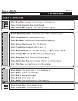
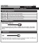


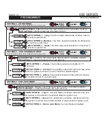


ADDITIONAL CONNECTORS
AUXILIARY SENSOR INPUT
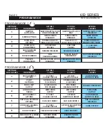
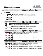
SYSTEM PROGRAMMING -
Menu 1
PAGE 8
650 SERIES
INSTALL MANUAL
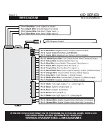
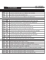
SYSTEM WIRING
SYSTEM PROGRAMMING -
Menu 1
PAGE 9
650 SERIES
INSTALL MANUAL
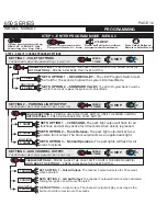
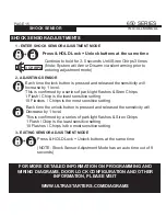
TRANSMITTER PROGRAMMING
LED
PROGRAM SWITCH
PIN 4
RED
PIN 3
BLACK
PIN 2
GREEN
12 VOLT OUTPUT FOR AUXILIARY SENSOR.
GROUND OUTPUT FOR AUXILIARY SENSOR.
FULL TRIGGER INPUT FOR AUXILIARY SENSOR.
PIN 1
BLUE
WARN-AWAY INPUT FOR AUXILIARY SENSOR.
PROGRAMMING SWITCH
STATUS LED
Plug the Program Switch into the Blue connector on the alarm module. This switch is
used for Remote Programming, Service/ Valet Mode and for changing programmable
features.
Plug the Program Switch into the Red connector on the alarm module. The LED is used
to determine alarm status and flashes during programming.
NOTE: ALL REMOTE’S TO BE USED MUST BE PROGRAMMED IN SEQUENCE
WHILE IN REMOTE PROGRAM MODE, RE-ENTERING REMOTE PROGRAM MODE
WILL ERASE ALL PREVIOUS REMOTE’S
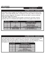
Turn ignition key OFF to exit remote program mode when all
required remote’s have been programmed.
8 -
REPEAT STEP 6 IF A SECOND REMOTE IS TO BE PROGRAMMED FOR 2ND CAR / PADLOCK OPERATION
Siren will Chirp 1 time to confirm remote has been programmed
(If siren does not chirp press button again)
7 -
Press & Release BUTTON 4 on Remote to be Programmed for
2ND CAR OR PAD LOCK
6 -
REPEAT STEP 4 IF A SECOND REMOTE IS TO BE PROGRAMMED FOR NORMAL OPERATION
Siren will Chirp 1 time to confirm remote has been programmed
(If siren does not chirp press button again)
5 -
Press & Release LOCK button on 1st Remote to be
Programmed for Normal Operation
If remote(s) are to be
programmed for "PADLOCK" skip and goto step 6
4 -
PROGRAMMING REMOTE’S
1 chirp confirms program mode entered followed by
5 chirps confirming transmitter program mode
3 -
Press and HOLD the valet switch, siren will chirp ONCE
(If siren does not chirp repeat step 1)
CONTINUE TO HOLD until siren chirps 5 times
2 -
Cycle the Ignition Key - ON/OFF ON/OFF ON
(Leaving the key ON)
1 -
ENTERING REMOTE PROGRAM MODE
The system can lean up to 4 different remote’s. Each remote to be used MUST be programmed
together during the same sequence. For security, when a new remote is programmed all
previous remote’s are deleted. Please see remote operation chart for information on using
Second Car / Pad Lock Operations
.


