background image




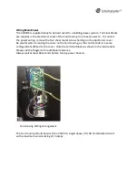
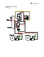
The DX2000 is set to provide a constant pressure inside the main duct despite the flow 
changes.  The main control board DCC7545 and a feedback pressure transducer:  Veris 
PXDLX01S are used to accomplish the function. Both the DCC7545 and the transducer are 
powered by the 24VAC power.  
 
The transducer is mounted on the duct monitoring the inside pressure. The output signal is 
a DC signal varying from 0V~10V. The DCC7545 takes the signal as a feedback and uses the 
PID control strategy to maintain a constant pressure inside the duct which can be set by 
three jumpers on the DCC7545.   
 



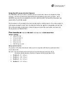
Model: 

PXDLX01S

  Manufacturer: 

VERIS INDUSTRIES


Jumper Settings: 


JP8 Set to FAST 


JP7 Set to IN W.C 


Jp5 Set to UNI 


JP4 Set to 10V 


OUTPUT Set to Volt 

Rotary Switch Position:  

The position of the flow transducers rotary switch corresponds with the RecoupAerator Main 
Control Board JP5.  
Example: Transducer Rotary Switch in Position 2 requires the RecoupAerator JP5=0   
                   Transducer Rotary Switch in Position 3 requires the RecoupAeraotor JP5=1 


Position  0

 - 0.1    inch w.c. 


Position  1

 - 0.25  inch w.c. 


Position  2

 - 0.5    inch w.c. 


Position  3

 - 1.0    inch w.c.


Summary of Contents for RecoupAerator 2000DX

Page 1: ... 178 Mill Street Athens Ohio 45701 740 594 2277 ultimateair com info ultimateair com ...

Page 2: ...ting stale air The 2000DX is an Energy Recovery Ventilator ERV meaning the RecoupAerator recovers and transfers air temperature and moisture from the stale outgoing air to the incoming fresh air No matter what the season you stay comfortable while breathing fresh clean air In addition to having an energy transfer rating of up to 95 the RecoupAerator moderates indoor humidity in the winter and turn...

Page 3: ...height feet The 2000DX controls are custom per installation The 2000DX has four 18 dia duct connections Please see illustrations contained in this manual Both housings have removable doors at each duct connection for access to the interior for maintenance All user performed maintenance will occur in the Wheel Housing The Fan Housing contains no user adjustable or replaceable parts Patented random ...

Page 4: ...apability of setting continuous flow within the operating flow range of 200 2000 CFM Boost input external control input pressure input are available Serviceability The unit is designed in two main housings wheel housing and fan housing The unit can be split in two for transport service and installation Each of the two housings have two doors for ease of service The wheel is accessible for cleaning...

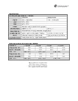
Page 5: ...lars 18 Dia inch 4 Round Collars 458 Dia mm MAINTENANCE Yearly filter service light maintenance STATION 1 outside supply 2 inside supply 3 inside exhaust 4 outside exhaust Temperature C 34 7 26 0 24 0 32 6 Relative Humidity 50 3 62 5 49 5 43 9 SRE 70 TRE 53 LPC 0 43 ASE 85 Temperature C 0 0 20 3 22 0 4 8 Relative Humidity 75 3 37 8 39 4 76 5 SRE 83 TRE 79 LPC 0 69 ASE 96 SRE Sensible recovery effe...

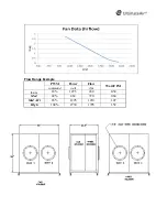
Page 6: ... PWM Power Flow Watt CFM command watt cfm Low 18 129 5 240 0 54 Med 42 462 720 0 64 Med Hi 65 1295 1210 1 07 High 100 2730 1795 1 52 ...

Page 7: ...r maintenance purposes See Airflow Diagrams for duct connection locations and airflow designations these are also labeled on the unit It is recommended that there be at least 36 of clearance at each duct connection point to ensure there is enough room to remove the doors To facilitate easy duct removal for maintenance make a portion of each duct section 24 to 36 easily removable ...

Page 8: ...nics cover Be careful when removing the cover on the Fan Housing as the control knob is in some configurations affixed to the cover Wire the terminal blocks as shown in the illustrations Please see the Diagrams for additional reference Always wait at least 60 seconds before turning power back on Fan Housing Wiring Arrangement The Fan Housing should be wired to a 240 VAC single phase 50 60 Hz dedic...

Page 9: ...ses the PID control strategy to maintain a constant pressure inside the duct which can be set by three jumpers on the DCC7545 Model PXDLX01S Manufacturer VERIS INDUSTRIES Jumper Settings JP8 Set to FAST JP7 Set to IN W C Jp5 Set to UNI JP4 Set to 10V OUTPUT Set to Volt Rotary Switch Position The position of the flow transducers rotary switch corresponds with the RecoupAerator Main Control Board JP...

Page 10: ...JMP2 1 JMP3 1 0 5 IN W C JP5 1 Range 1 0 IN W C o JMP2 0 JMP3 0 0 1 IN W C o JMP2 0 JMP3 1 0 3 IN W C o JMP2 1 JMP3 0 0 5 IN W C o JMP2 1 JMP3 1 0 7 IN W C Manual Override is allowed in some scenarios To enable override JP4 1 When the override is not enabled VR and BLWR must connected together via jumper wire JP4 1 JP3 REM Wall Controller Override JP4 1 JP3 0 10V 0 10V input Override JP4 0 No Over...

Page 11: ... ...

Page 12: ...ntrol will default to the higher flow position being the command from the CO2 monitor or via the dial control The RecoupAerator is EconoCool equipped so that you can make use of outside air in summer e g during the night to cool your building thereby providing AC energy savings Using a temperature sensor on the incoming air stream and a sensor on the room temperature the RecoupAerator automaticall...

Page 13: ...178 Mill Street Athens Ohio 45701 740 594 2277 ultimateair com info ultimateair com For more information and or ordering replacement parts please contact UltimateAir Inc Revised 9 19 2013 by MB ...

Reviews: