Installation Manual
UL
POWER
UL350i UL350i
F
UL350i
S
UL 350i
HPS
350i
SA
MI 350A01 Revision No: 7
Date:
2014-09-15
Page:
49
of
60
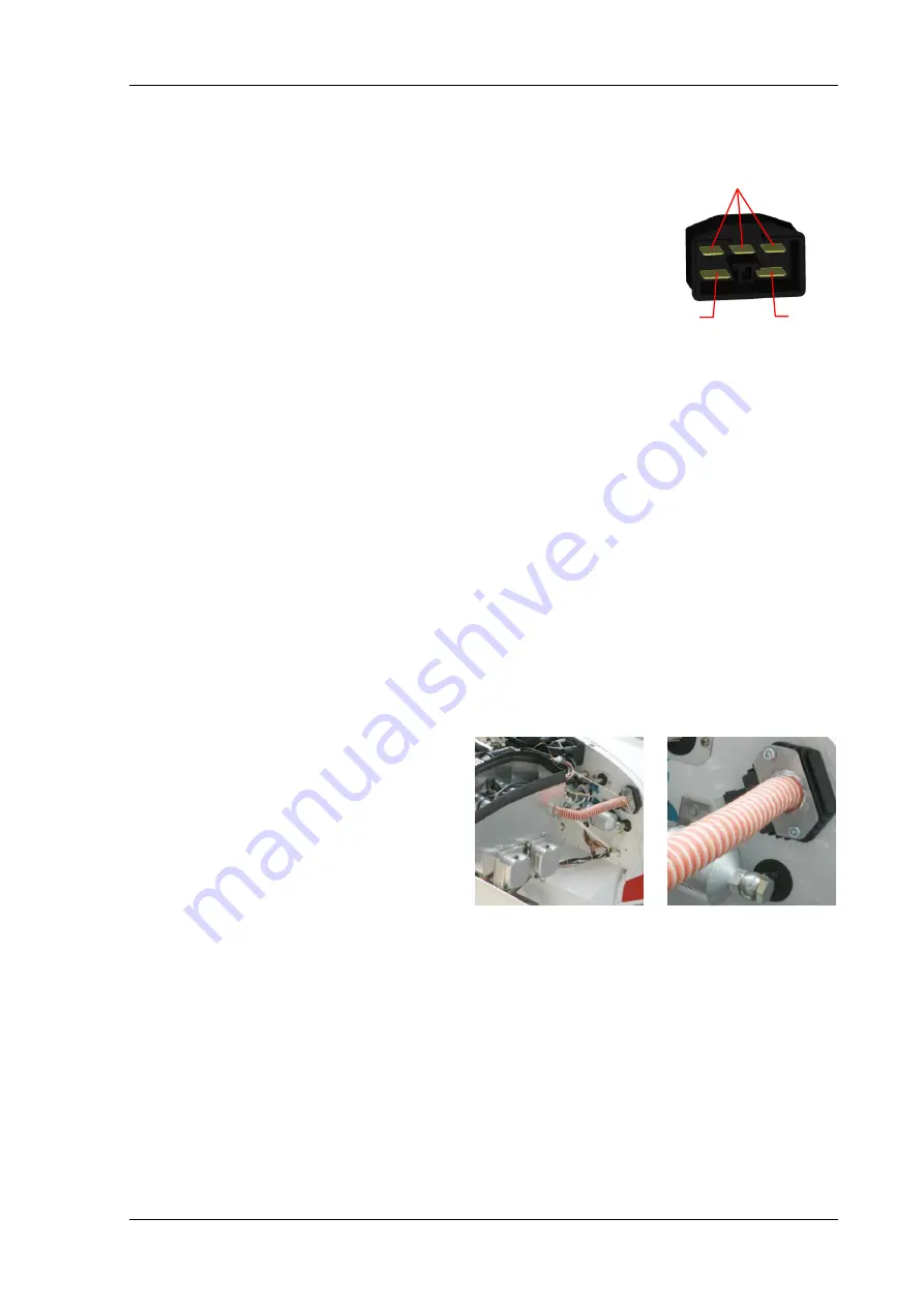
E xte n s io n o f ye llo w w ire s
3 -p h a s e a lte rn a to r (in a n y o rd e r)
B a tte ry (+ )
B a tte ry (-)
Connect regulator/rectifier to the battery and the 3 yellow electrical
wires (3) (which are usually grouped together in a protective sheath)
coming from the alternator as shown on the right (plastic connectors
and metal pins are provided).
Make sure all wires, pins and connectors are properly connected and
make good contact. Use electrical conductors with a cross section of
at least 6mm² (10AWG ) to connect to battery. When the distance
from the regulator to the battery is more than 1.5 metre ( 5 feet ),
use 10 mm² (8 AWG). Fasten wires to engine mount/firewall in such
as way to minimise vibration. Vibration is a major cause of connection
and wire breakage. Keep them well away and shielded from the exhaust.
Since the permanent magnet 3-phase alternator provides a constant current, which is only
depending on engine rpm, a “shunt’ regulator/rectifier is used. As the overall power usage for the
engine and accessories used in recreational aircraft is usually relatively low, the use of a shunt type
is the simplest and most reliable type of regulator with fail safe characteristics. A disadvantage of a
permanent magnet alternator is that it is always providing the electrical current associated with the
rpm which is independent of the actual current needed at any particular moment, making it run
hotter than it would actually need to be. After the engine’s starting and once the battery is again
fully charged and its voltage reaches a certain fixed value, the thyristors in the shunt regulator
actually short the generator windings to ground (dump the load) in a pulsating like fashion which
generates heat in the regulators components and which must be dissipated by its outside surfaces to
the surrounding environment to prevent the regulator/rectifier from overheating and
malfunctioning.
Although the cooling fins of the RR are presumably large enough to ensure proper cooling on their
own, the RR manufacturer would undoubtedly expect that the RR is placed in a well ventilated and
relatively cool environment. If the firewall is made of wood or other non heat conducting material
with the fire proofing obtained by use of special coatings, metal foil etc. it is possible that this type
of surface does little or nothing to aid in heat transfer. Placing the RR in the cabin against a surface
covered with carpet for example, could create serious troubles. As with most electrical
components, overheating will cause failure!
Therefore the RR must be situated in a
relatively
cool
area
of
the
engine
compartment with sufficient cool air
ventilation. Ideally the RR should be placed
in a constant stream of cool air to make sure
heat dissipation is always at its maximum.
The pictures on the right show an example of
cooling air being ducted from the cylinder
head baffles directly on top of the RR.
Cooling air for the alternator is drawn from
the back of the engine by the metal fan on the inside of the starter ring gear. This air is then
pushed through the space between the stator windings and out against the engine back plate. The
requirement of cool air availability is also of major importance for the alternator.
Summary of Contents for UL35Oi
Page 2: ......


