


Page 8
M4220170607EN
UI Robot Technology Co. Ltd.
UIM2842
Standalone Operation
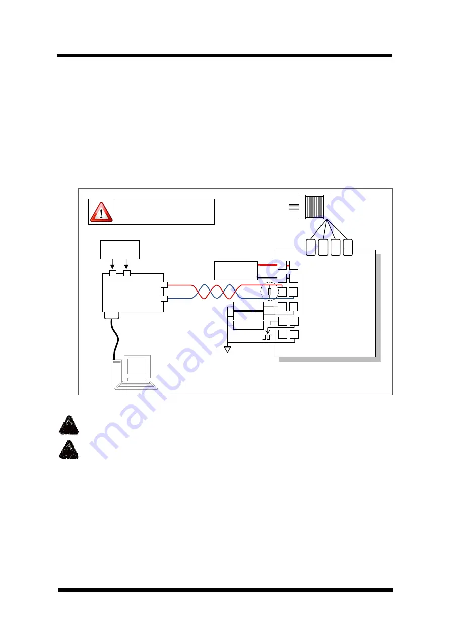
When working standalone, user can use the wiring scheme shown in figure 0-3.
Please note that, this wiring scheme should be used for setting the ID of a UIM2842
controller.
For long distance transfer, both ends of the CAN bus should be terminated with120Ω
terminating resistors. As UIM2501 converter has a build-in terminating resistor, user only
needs to attach a resistor at the other end of the bus. Please refer to the UIM2501 user
manual for how to enable the UIM2501 converter’s terminating resistor. CANH and CANL
should use a twisted wire pair.
Figure 0-3
:
Wiring Scheme for Standalone Operation
Warning:Hot plugging is forbidden.
Warning: All controllers, gateways and subscriber equipments must be common-
grounded.
Except supply voltage port and
motor terminal, voltage on port
must be kept between -0.3~5.3V.
UIM2842
Controller
12
11
8
7
5
3
4
6
CANH/CANL
VCC
GND
S1/S2
S3/P4
1
A-
A+
B+
B-
2
+5V/AG
10
9
12 - 28VDC
Power Sipply
UIM2501
Converter
CAN
L
RS232 Cable
DB9 Port
1
2
3
4
CANH
Twist Wire
Pair
120
6 - 40VDC
Sensor 1
Sensor 2
Sensor 3
Stepper Motor


