background image

11

1 TECHNICAL CHARACTERISTICS

The manufacturer reserves the right to make

changes without any prior notification.

2 INTRODUCTION

It is necessary to Read this instruction manual ca-

refully to know the specifications of the dispenser.

As all mechanical products, this unit requires cle-

aning and maintenance. Its working order can be

compromised by possible errors made by the

operator during disassembly and cleaning. For

this reason it is important that the staff in charge

of the dispenser is qualified to carry out the day to

day operations, which are dismantling, cleaning,

sterilisation and reassembly.

3 INSTALLATION

1

Remove the dispenser from the packaging.

(This should be kept for any future requirement) 

2

Check the dispenser has not been damaged

during transport. The forwarding agent must be

notified immediately of any claim.  

3

Install the dispenser on a counter top that will

support its weight, even with a full load. 

4

Before connecting the dispenser electrically

check that the voltage (in the network) is as

shown on the data plate. Plug the unit into a

grounded, protected single phase electrical sup-

ply according to the applicable electrical codes

and the specifications of your machine. If you

want to make a fixed connection to the network,

connect the cord to a bipolar wall breaker with a

contact gap of at least 3mm. not use extension
cords to connect the unit electrically. 

5

The dispenser does not leave the factory

presanitized and sanitized. Prior to use it must be

disassembled, cleaned and sanitized according

to the instructions in chapter 7 CLEANING AND

SANITIZING PROCEDURES. 

4 TO OPERATE PROPERLY AND 

SAFELY

1

Read the instruction booklet before using the

dispenser.  

2

Use the dispenser only if it is grounded cor-

rectly. 

3

Do not use extension cords to connect the

dispenser electrically. 

4

Do not operate the dispenser if it is not clo-

sed and blocked with screws. 

5

Do not place fingers or objects in the cooling

fissures and faucet outlet panels louvers.

6

Do not remove the container when the unit is

in operation.

7

This unit is not meant to be used outside.

8

This unit is not to be installed in areas

subject to water-spouts.

9

Do not use water-jets to clean the unit.

10

This unit can work in a room temperature

range b5° and +35°C.

Delice

Transparent removable bowls

n

1

Capacity of each bowl, approx.

l

5

Dimensions:

 width

cm

24

depth

cm

32

height

cm

49

Net weight, approx.

kg

6

Gross weight, approx.

kg

7

Adjustable thermostats

n

1

Noise level lower than 70 dB (A)

IMPORTANT

Electric specifications: read the informa-

tion on the data plate of each single

dispenser, situated on the underside. The

serial number of the units is preceded by #

ATTENTION

Ensure that the unit is grounded correctly;

if not it may cause electric shock to per-

sons or damage the dispenser.

ATTENTION

Do not remove the container until the hot

plate is cold.

ATTENTION

Do not remove the container from the

dispenser when it contains hot products.

Summary of Contents for Delice

Page 1: ...DELICE MANUALE D ISTRUZIONI OPERATOR S MANUAL CARNET D INSTRUCTIONS GEBRAUCHSANWEISUNG MANUAL DE INSTRUCCIONES...

Page 2: ...rato DISTRIBUIDOR DE BEBIDAS CALIENTES Marca UGOLINI S p A Fabricante UGOLINI S p A Modelo DELICE DELICE SILVER DELICE GOLD 230V 50Hz responden con las siguientes Normativas En cumplimiento de las Nor...

Page 3: ...tto da parte del detentore comporta l applicazione delle sanzioni amministrative previste dalla normativa vigente Pursuant to the European Directives 2002 95 EC 2002 96 EC and 2003 108 EC on restricti...

Page 4: ...ontato lavato e sanitizzato seguendo quanto previsto nelle presenti istruzioni al capi tolo 7 PULIZIA 4 PER UN FUNZIONAMENTO SICURO E CORRETTO 1 Non usare il distributore prima di aver letto il presen...

Page 5: ...sualizzazione della temperatura gradi centigradi C o Fahrenheit F ed il simbolo che indica l accensione dell elemento riscal dante All accensione vengono avviati tanto il riscalda mento quanto il disp...

Page 6: ...l distributore agendo sull interruttore gene rale C e riaccenderlo tenendo premuto il tasto A Sul display verr mostrato il tempo di cottura espresso in minuti che potr essere diminuito o aumentato uti...

Page 7: ...ONTAGGIO 1 Inserire cassetto raccogligocce e griglia nella sua sede 2 Lubrificare il pistone rubinetto nella zona A indicata in figura 2 utilizzando esclusivamente grasso per uso alimentare figura 2 3...

Page 8: ...8 DELICE...

Page 9: ...vento del Protettore termico Controllare il voltaggio della presa di corrente Controllare la viscosit del prodotto Controllare la ventilazione alette dei pannelli laterali ostruite o parte inferiore d...

Page 10: ...termostato di servizio posto a lato del distributore regolato a una temperatura troppo bassa Regolarlo alla temperatura opportuna Prodotto eccessivamente diluito Aumentare concentrazione del prodotto...

Page 11: ...unit electrically 5 The dispenser does not leave the factory presanitized and sanitized Prior to use it must be disassembled cleaned and sanitized according to the instructions in chapter 7 CLEANING A...

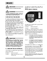
Page 12: ...wing On the display the symbols C or F indicates the current temperature unit and the symbol in dicates the turning on of the heating element When the dispenser is turned on both the mixing and the he...

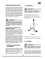
Page 13: ...length of the Cooking Cycle is shown and it is possible to decease or increase it using keys A or B and to confirm it pressing both keys together 7 CLEANING AND SANITIZING PROCEDURES Cleaning and san...

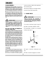
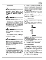
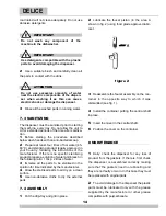
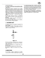
Page 14: ...LY 1 Put the drip tray and grill in place 2 Lubricate the faucet piston in the area A shown in fig 2 using food grade approved lubri cant figure 2 3 Reassemble the faucet assembly on the con tainer in...

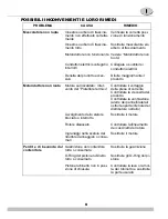
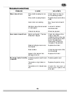
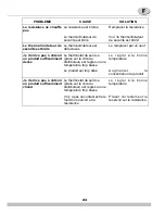
Page 15: ...ted Thermal Protection tripped Check the voltage of the outlet Check the ventilation fins on the side panels obstructed or lower part of the distributor obstructed Check the viscosity of the product S...

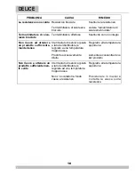
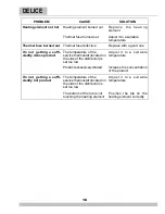
Page 16: ...e service thermostat located on the side of the distributor is set too low Adjust it to a suitable temperature Product excessively diluted Increase the concentration of the product I m not getting a s...

Page 17: ...lez r aliser un branchement fixe au r seau branchez le c ble un dispositif bipolaire de coupure fix au mur dont les ouvertures de con tact sont d au moins 3 mm N utilisez pas de ral longe pour branche...

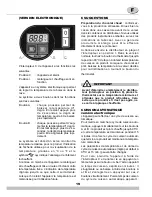
Page 18: ...positif d agitation continuera fonctionner 7 Le distributeur est quip d un conteneur fond clos amovible afin de faciliter les op rations de nettoyage et d sinfection 5 1 DESCRIPTION DES COMMAN DES Le...

Page 19: ...e pour la distribution en tournant le bouton du thermostat CUISSON AUTOMATIQUE version electronique L appareil peut effectuer un cycle de cuisson au tomatique Pour mettre en marche le cycle de cuisson...

Page 20: ...t endommager les pi ces laver et une solution trop dilu e peut ne pas nettoyer correctement N utilisez pas de produits abrasifs 2 Utilisez une brosse adapt e et lavez soi gneusement l aide de la solut...

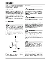
Page 21: ...lle les gouttes et la grille en place 2 Lubrifiez le piston robinet dans la zone A indiqu e sur la figure 2 uniquement avec la graisse usage alimentaire figure 2 3 R assemblez le robinet sur le conten...

Page 22: ...tor ducteur ne tourne pas Le moteur est surchauff intervention du protecteur thermique Contr ler le voltage de la prise de courant Contr ler la ventilation ailettes des panneaux lat raux obstru es ou...

Page 23: ...e Le thermostat de service plac sur le c t du distributeur est r gl sur une temp rature trop basse Le r gler la bonne temp rature Le produit est trop dilu Augmenter la concentration du produit Je n ar...

Page 24: ...n werden soll so muss das Kabel an einen zweipoligen Wandschalter mit einer Kontakt ffnung von mindenstens 3 mm angeschlossen werden F r den elektrischen Anschluss des Ger tes keine Verl ngerungskabel...

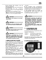
Page 25: ...hlossenem Boden auf der zur Vereinfachung der Reinigung und Hygienisierung entfernt werden kann 5 1 BESCHREIBUNG DER BETRIEBSSCHALTER Der Distributor weist einen Hauptschalter mit den folgenden Funkti...

Page 26: ...gsprozess durch Dies bedeutet dass das Produkt auf 95 C erhitzt und bei dieser Temperatur f r 15 Minuten gehalten wird Danach wird das Produkt auf der voreingestellten Temperatur gehalten Die Temperat...

Page 27: ...mit dem Getr nk in Kontakt kommen sorgf ltig mit der Reinigungsl sung reinigen 3 Alle gereinigten Bauteile unter flie endem Wasser absp len ACHTUNG Vor dem Abbauen von Komponenten die Stromversorgung...

Page 28: ...den Lappen verwenden 7 4 MONTAGE 1 Die Tropfschublade und den Rost in seinen Sitz einsetzen 2 Den Kolben des Hahns in Bereich A gezeigt auf Abbildung 2 ausschlie lich mit einem lebenmitteltauglichen F...

Page 29: ...ch nicht Motor berhitzt Thermo schutz ausgel st Die Spannung des Stromanschlusses pr fen Die Bel ftung pr fen Lamellen der Seitenw nde oder unterer Teil des Verteilers verschlossen Die Viskosit t des...

Page 30: ...Produkt zu erzielen Das Betriebsthermostat seitlich des Verteilers ist auf eine zu niedrige Temperatur eingestellt Auf die entsprechende Temperatur einstellen Produkt zu stark verd nnt Die Konzentrat...

Page 31: ...a a tierra en conformidad con las normas vigentes Si se quisiera realizar una conexi n fija a la red conectar el cable a un interruptor de pared bipolar con una apertura para los contactos de al menos...

Page 32: ...ibuci n El dispositivo de agitaci n seguir funcionando 7 El distribuidor dispone de contenedor con fondo cerrado extra ble para facilitar las operaciones de limpieza y saneamiento 5 1 DESCRIPCI N DE L...

Page 33: ...A versi n electr nica El distribuidor dispone de un ciclo de cocci n au tomatica Dicho ciclo conlleva al calentamiento del producto a una temperatura de 95 C y lo mantiene a esta temperatura durante 1...

Page 34: ...uede no limpiar lo suficiente No usar detergentes abrasivos 2 Usar un cepillo adecuado y lavar con cuidado con la soluci n detergente todas las piezas en contacto con la bebida 3 Enjuagar con agua cor...

Page 35: ...el caj n recogegotas y la rejilla en sus alojamientos correspondientes 2 Lubricar el pist n del grifo en la zona A indicada en la Figura 2 utilizando exclusivamente la grasa adecuada para uso aliment...

Page 36: ...o intervenci n del Pro tector t rmico Comprobar el voltaje de la toma de corriente Comprobar la ventilaci n aletas de los paneles laterales o parte inferior del distribuidor obstruidas Comprobar la vi...

Page 37: ...o suficientemen te denso El termostato de servicio situado al lado del distribuidor est regulado a una temperatura demasiado baja Regularlo a la temperatura adecuada El producto est demasiado diluido...

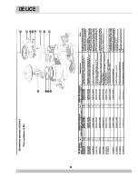
Page 38: ...stoff Arbol del contenedor de pl stico 4 22800 26488 Albero contenitore acciaio Steel bowl shaft Arbre du r servoir acier Zentralwelle stahl Arbol del contenedor acero 5 22500 01302 OR albero centrale...

Page 39: ...comandi nero Black side panel for controls Panneau lat ral pour contr les noir Seitenteil auf Kontrollen seite Panel lateral lado contro les nero 32 22800 26432 Pannello lato comandi oro Golden side p...

Page 40: ...pport dor plaque chauffante Goldfarbig halter f r Heiz platte Soporte para plancha calentadora oro 3 10554 44000 Clip M4 M4 Clip Clip M4 Klip M4 Clip M4 4 22800 26415 Blocchetto portabulbo Thermostat...

Page 41: ...enedor oro 22 22800 26414 Mescolatore Mixer M langeur R hrwerk Mezclador 23 22800 26412 Albero contenitore Bowl shaft Arbre du r servoir Zentralwelle Arbol del contenedor 24 22800 26419 OR albero cent...

Page 42: ...e Gear motor Motor ducteur Motoruntersetzung Motoreductor ELECTRONIC VERSION 1 Interruttore Switch Interrupteur Dreiwegeschalter Interruptor 2 Termofusibile Termic fuse 3 Motoriduttore Gear motor Moto...

Page 43: ...43...
Page 44: ...2448_99 R7 1 12B17 Ugolini spa Via dei Pioppi 33 20090 Opera MI Tel 02 530059 1 Fax 02 530059260 www ugolinispa com E Mail sales ugolinispa com...

Reviews: