Page: 12
< Librae instruction manual
3 Installation
3 Installation
Librae instruction manual >
Page: 13
3.6 Intended Use
The Librae Incapacitance Tester is intended for
investigation use on laboratory animals only.
3.7 Additional Safety Considerations
1. Use Ugo Basile accessories and parts only
2. Immediately disconnect and replace a damaged power cord
3. Do not obstruct easy access to the power module
4. Do not obstruct the grids on the sides of the cabinet, see paragraph 3.4
5. Do not operate in hazardous environments or outside prescribed environmental limita-
tions, see paragraph 6.0
6. Do not spray any liquid on the connectors, display, or other parts
Ugo Basile cannot in any way and form be held responsible for damage caused to things and
people due to:
• Incorrect electrical supply
• Incorrect installation procedure
• Incorrect or improper use or, in any case, not in accordance with the purpose for which the
instrument has been designed and the warnings stated in the instruction manual supplied
with the instrument
• Replacement of original components, accessories or parts with others not approved by the
manufacturer
• Servicing carried out by unauthorized personnel
See also paragraphs 2.1.1 and 2.1.2
3.8 Connection
Connect the mains cord between the power socket of the Librae and the power outlet, provided
with a reliable earth connection.
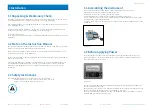
Connect the pedal switch to the Librae Incapacitance Tester (blue bushing Figure 3.8.1). Note
that the connector of the pedal switch is provided with a polarization key; align it with the blue
bushing, and gently push in.
To remove the connector, gently pull out.
DO NOT ROTATE THE CONNECTOR: PERMANENT DAMAGE WILL OCCUR
Figure 3.8.1
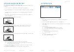
The connection module on the front panel (Figure 3.8.2) encompasses the following
connectors, from let to right:
1. Upper and lower USB ports: enable data exchange (configurations & results) with a PC, and
allows firmware upgrades, via the USB flash drive provided in the box (see paragraph 4.7.1)
2. TTL I/O: 15pins D-SUB connector, provides TTL input and output for start/stop command
and mode settings (see paragraph 4.8.1 for pin-out configuration)
3. COM: Reserved for maintenance and service purpose
4. Ethernet connector: Reserved, not to be used
Figure 3.8.2
USB Hard Disk
If the internal memory is corrupted, the Instrument will ask you to insert a USB memory key
into the lower USB port. This allows you to run the experiment.
The instrument needs to be checked by UGO BASILE personnel for maintenance.


