Page: 10
< Librae instruction manual
3 Installation
3 Installation
Librae instruction manual >
Page: 11
3 Installation
3.1 Unpacking & Preliminary Check
Check the contents of your shipment (see “What is in the box?” page at the start of this manu-
al), and visually inspect the instrument as you take it out of the packaging.
If the instrument appears to be damaged, inform the carrier immediately and send an email to
If after having tested the instrument, it fails to meet normal performance standards, please
contact our after sales service, see paragraph 5.4-Customer Support.
Protect the environment:
Please dispose of packaging according to existing and applicable waste management rules and
regulations.
3.2 Note on the Instruction Manual
This Instruction Manual included in the box (on the USB pen drive in a PDF form) is necessary
for the correct installation and operation of the instrument.
We recommend reading the manual carefully, as it is essential for understanding the correct
installation and operation of the instrument.
Please save the manual, ready for consultation by the qualified personnel using the instrument.
Print it, only if necessary.
Our Instruction Manuals are available as free downloads on our web site, www.ugobasile.com
For any additional information and/or assistance, you are welcome to contact our Service
Department (see paragraph 5.4-Customer Support), specifying the serial number of your
instrument.
3.3 Safety Instructions
The following guidelines must be followed to ensure safe operation.
DO NOT attempt to open the cover or perform any service work
DO NOT connect human subjects to the device
3.4 Assembling the instrument
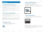
Place the instrument on a stable and flat surface where it will be used for tests.
Adjust the four rubber feet until the instrument is level.
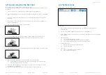
Position the mouse or rat restrainer onto the base plate.
Do not lift or move the combined instrument when assembly is completed.
Do not incline the device, as the Perspex restrainer may accidentally fall off the plate. Please
do not block the lateral ventilation grids.
For proper performance, ensure there is a free space of 20cm on the left, right and rear of the
instrument.
Figure 3.4.1
3.5 Before Applying Power
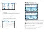
The Power Module (see figure 3.5.1) is positioned on the left hand side of the back panel,
which encompasses – from left to right - the fuse holder, the main ON/OFF switch and the
inlet connection of the power cord.
Figure 3.5.1
The two-pole toggle switch, which complies with international safety standards, allows you to
turn the instrument ON or OFF.
The fuse holder uses two fuses. Use (T400mA) slow-blow fuses for operation at both 115 or 230
Volts, for fuse replacement, please refer to paragraph 5.1-Electrical.
The power cord inlet fits a standard C13 cable, Cat. # E-WP008. Ensure your power out-take is
provided with a reliable ground connection.


