background image

2 x CP

2 x Po

2 x M

2 x Ne

1 X U

Note

by a P

cable

suppl

cable a

Get Started to Know Your W

Pack

2 * CPE820 Gigabit Bridge
2 * Gigabit POE Adapter (24V)
2 * Cat 5e Network Cable
2 * Metal Hoop
1 * User Manual

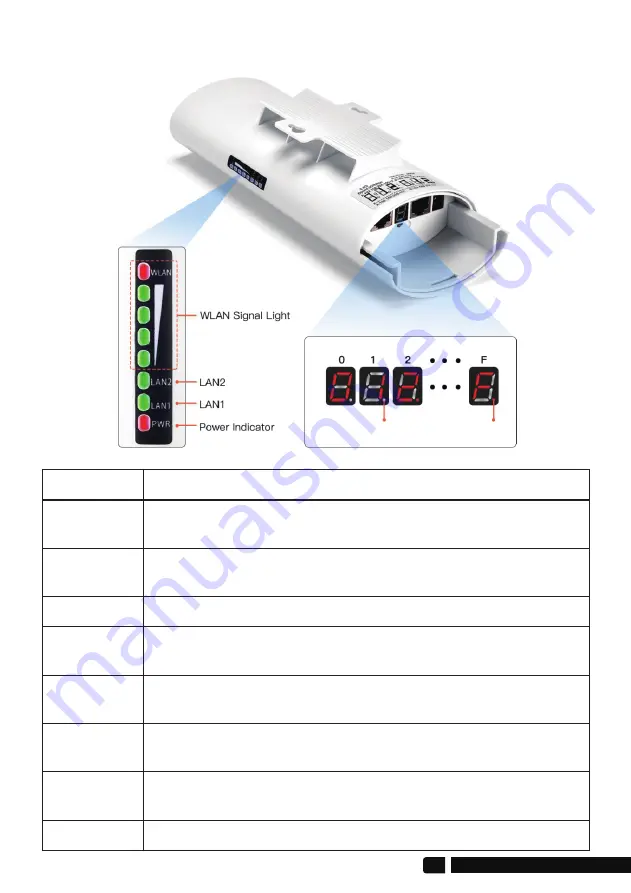
6.LED Indicator Details

Description

After the bridge is connected successfully, the WLAN light will 

be on, not connected the WLAN light will not be lit.
The data connection is successful, the LED light is on, 

otherwise, it is not bright.
Power indicator, the LED is on after the power is connected
Digital display LED display "H" indicates manual configuration 

status
Digital display LED display "L" and flashing indicates settings 

status
Digital display LED flashing indicates edit the config or 

connecting

LED Light

Signal Lights

LAN1/LAN2

PWR

Digital Tube

Digital Tube

Digital Tube

Display that a fixed number is solid, it means that the two 

bridges are paired successfully and are working.
A, B status lights, lighting is B mode, no lighting is A mode.

Digital Tube

Point Light

04

[email protected]

Transmitter B Mode

Receiver A Mode

Summary of Contents for CPE-820

Page 1: ...he manual carefully before use If there are any problems during the use please contact us in time The installation of this device requires some network knowledge If you can t install it please let us know or contact a professional Customer Service Email support ueevii com Model CPE 820 USER MANUAL ...

Page 2: ...nt CPE is widely used in highways reservoir river monitoring elevator monitoring systems site crane monitoring systems port terminal monitoring systems marine aquaculture monitoring systems and so on Point to point extend network WiFi range extend the network in the house to your barn garage church warehouse and even neighbor s house through wireless bridge signal transmission No need to install a...

Page 3: ...6M 130M 144 4Mbps 433Mbps Direct Sequence Spread Spectrum DSSS OFDM BPSK QPSK CCK DQPSK DBPSK IEEE802 11ac IEEE802 11n IEEE802 11a IEEE802 3u CSMA CA TCP IP IPX SPX NetBEUI DHCP NDIS3 NDIS4 NDIS5 4900 6100MHz 3W POE 24V 1A 48V 0 5A 16dBi Horizontal 60 Vertical 30 Support Support Model CPU Flash DRAM Interface Data rate Transfer method Modulation Protocol standard Agreement Frequency Range Power An...

Page 4: ... toggle a different character to pairing 5 1 Button Operation A B Button Pushing the button to A indicates that the bridge acts as the master bridge transmitter and pushing the button to B indicates that the bridge acts as the slave bridge receiver 5 Interface Details Reset Button 100Mbps LAN A B Button Digital Tube DC Unavailable 1000Mbps B LED Gigabit PoE Adapter LED PoE Port 1000Mbps LAN Port su...

Page 5: ...se it is not bright Power indicator the LED is on after the power is connected Digital display LED display H indicates manual configuration status Digital display LED display L and flashing indicates settings status Digital display LED flashing indicates edit the config or connecting LED Light Signal Lights LAN1 LAN2 PWR Digital Tube Digital Tube Digital Tube Display that a fixed number is solid it mea...

Page 6: ...N port of the wireless bridge 1 2 The LAN port of the PoE power supply is connected to the PC router and switch 2 Point to Point Pairing Step 1 Switch one unit to A Master Bridge and one unit to B Slave Bridge 2 Connect the POE to each unit using the Ethernet cable and plug the POE in 3 Wait for them to power up about 2 min 4 Use the tiny reset button to click through until you get a channel with ...

Page 7: ...gnal light on the side turns on it means their pairing is successful 7 Finally connect other devices Router PC Switch and install them to the target location 4 Installation 1 Place the CPE to the selected position and adjust the CPE front panel orientation to be approximately the same as the selected direction then use the ties to fix the CPE the bracket is not included in the package Recommended U...

Page 8: ...d on by default for the master bridge WiFi SSID CPE5G 5GXXX WiFi PWD zllinkcpe123456XXX XXX represents different channels please refer to the comparison table in the user manual 2 You can access the wireless bridge through your computer to set the SSID and new WiFi password Please refer to the advanced settings section 3 Connect the PoE adapter PoE to CPE and LAN to Camera PC Router or Switch based...

Page 9: ...etwork WiFi range 6 2 Case 2 Point to point extended of surveillance cameras range 6 3 Case 3 Point to multiple point extended surveillance cameras range IP Camera IP Camera IP Camera Switch DVR Computer Master Bridge Slave Bridge DVR Computer IP Camera IP Camera IP Camera IP Camera Master Bridge Slave Bridge 60 08 support ueevii com POE POE ...

Page 10: ...P Camera IP Camera Advanced settings Computer Access Note You can enable the device without advanced settings 1 Connect the CPE to the computer Refer to the figure left to connect the CPE to the computer through a PoE adapter and an Ethernet cable support ueevii com 09 100M port LAN AP POE Charger PC POE 1000M port ...

Page 11: ...twork properties Refer to the picture above to open Step 3 Find and double click open the Internet Protocol Version 4 TCP IPv4 choose the Use the following IP address and enter IP address subnet mask Default gateway Preferred DDS server 3 Change your computer s IP address to 192 168 188 xxx 192 168 188 xxx cannot be the same as the IP of the CPE then entry IP address is 192 168 188 xxx subnet mask...

Page 12: ...cessful go to setting 4 On the login screen the default user name and login password of the wireless bridge is admin just entry password login 6 In the wireless settings turn off Hide SSID then modify the SSID name and WiFi password and finally click Apply to complete the setting support ueevii com 11 ...

Page 13: ...You can check the SSID and password through this chart Ps In this chart SSIDs and Passwords are the default Digital IP WiFi Correspondence Chart 12 support ueevii com ...

Page 14: ...kcpe123456140 zllinkcpe123456149 zllinkcpe123456153 zllinkcpe123456157 zllinkcpe123456161 zllinkcpe123456165 Ps In this chart SSIDs and Passwords are the default Digital IP WiFi Correspondence Chart Troubleshooting Trouble 1 Use WiFi analysis to choose the best channel 2 CPE should be in the normal distance and avoid the wall 3 Adjust the angle of CPE according to signal strength Reason Solution 1...

Page 15: ...nce angle and channel to decrease latency 2 Check if port isolated to avoid network virus and broadcast storm 4 Decrease the access users 5 Change use a Cat 5e or above network cable 1 Packet Latency 2 Ethernet cable circuit 3 Network virus attack 4 Too much access users 5 Network Cables type lower than Cat 5e 1 Make CPE or PoE adapter need a ground connection 2 Running time over 7 days reboot it ...

Page 16: ...e read the manual carefully before use If there are any problems during the use please contact us in time B The installation of this device requires some network knowledge If you can t install it please let us know or contact a professional Tech Service Email support ueevii com support ueevii com 15 ...

Reviews: