EVK-JODY-W3 - User guide
UBX-20030840 - R02
Board description
Page 19 of 29
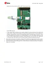
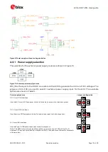
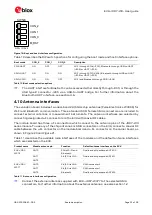
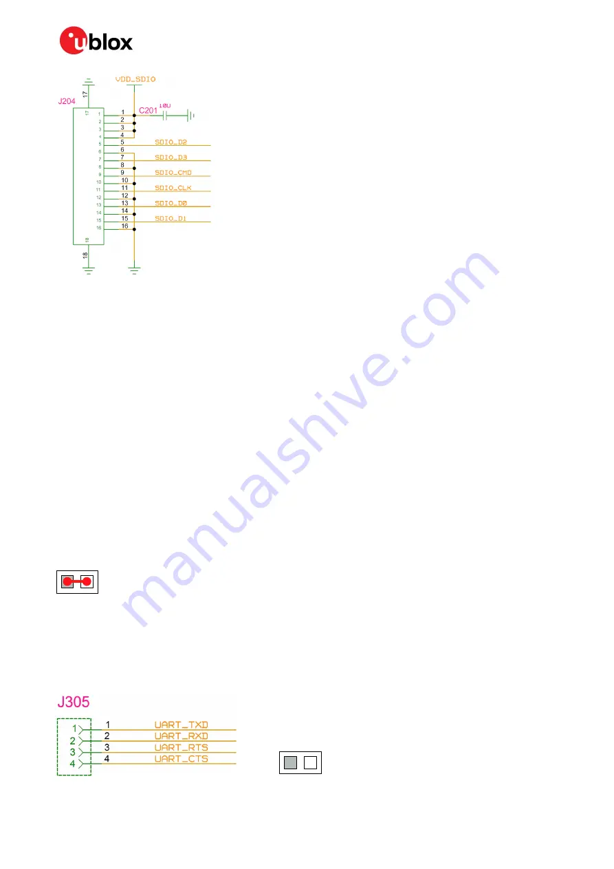
Figure 13: SDIO interface connector
All signals except
VDD_SDIO
are directly connected to the JODY-W3 module through 22
Ω
series
resistors connected on the module board.
VDD_SDIO
is connected to the power supply connector (J105) and is used for supplying 3.3 V for
VBAT
from the SDIO interface. The SDIO interface has 50
Ω
impedance. The SDIO signals are powered
by the
1V8
voltage domain.
☞
Pull-up resistors for the SDIO lines are not installed on the EVK because they are typically
included in the host CPU. The EVK carrier board has the provision to install pull-up resistors if
needed by the design.
4.6
Bluetooth UART interface
The Bluetooth UART interface of the JODY-W3 series module can be accessed either directly through
the UART pins on J305, or through the USB type-C connector via a USB-to-UART bridge (default).
A USB-to-UART bridge (FTDI FT234XD) is included on the evaluation board to connect to the high
speed UART interface of the JODY-W3 series module.
VDD_USB
from the USB connector is converted
by a DC-DC to 3.3 V and connected to the power supply connector (J104) for supplying
VBAT
from
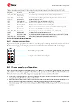
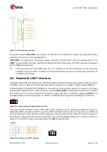
the USB interface. Place the jumper on J400 to use Bluetooth through the USB type-C connector.
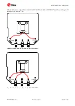
Figure 14: Jumper setting to use Bluetooth over USB
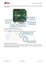
The 4-pin UART interface of the JODY-W3 series modules can be directly accessed through the
Bluetooth UART connector J305. To use the UART interface directly, remove the jumper on J400 and
connect the UART host interface to the respective module side pins on J305 as shown in Figure 15
and Table 8. Signal ground can be connected to one of the available GND pins on J303 as shown in
Figure 18. The UART signals are powered by the
VIO
voltage domain.
Figure 15: Bluetooth over UART interface
J400
J400

