EVK-JODY-W3 - User guide
UBX-20030840 - R02
Board description
Page 21 of 29
4.8
Other interfaces
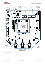
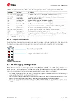
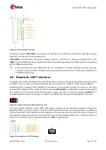
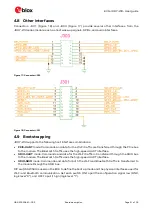
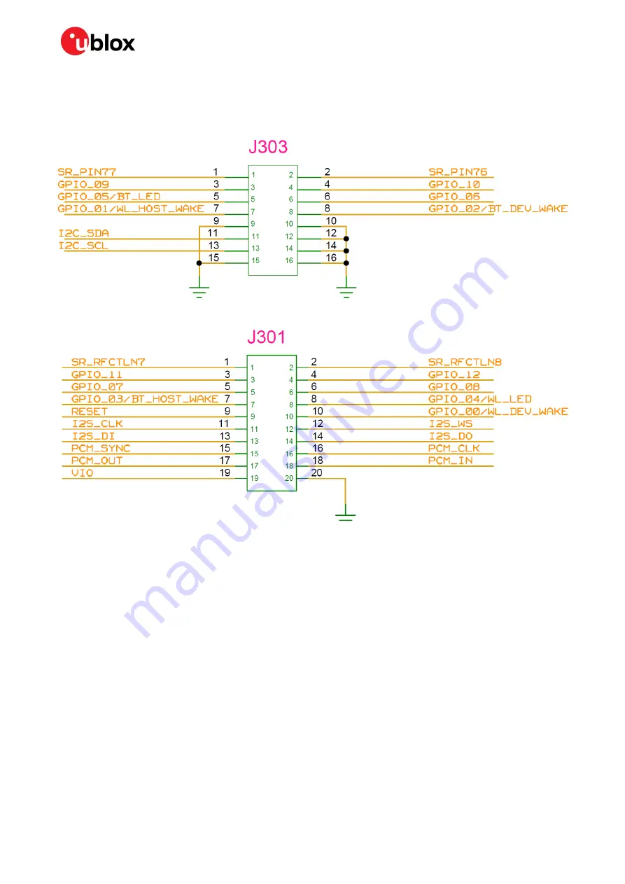
Connectors J301 (Figure 18) and J303 (Figure 17) provide several other interfaces from the
JODY-W3 series module, such as host wake-up signals, GPIOs, and audio interfaces.
Figure 17: Connector J303
Figure 18: Connector J301
4.9
Bootstrapping
JODY-W3 supports the following host interface combinations:
•
PCIE-UART
mode: Commands and data for the Wi-Fi traffic are transferred through the PCIe bus
to the module. The Bluetooth traffic uses the high-speed UART interface.
•
SDIO-UART
mode: Commands and data for the Wi-Fi traffic is transferred through the SDIO bus
to the module. The Bluetooth traffic uses the high-speed UART interface.
•
SDIO-SDIO
mode: Commands and data for both the Wi-Fi and Bluetooth traffic is transferred to
the module through the SDIO bus.
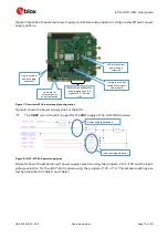
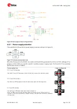
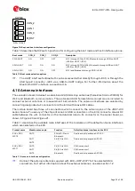
DIP switch SW503 is used on the EVK to define the boot up mode and the physical interfaces used for
Wi-Fi and Bluetooth communication. Set each switch ON to pull the configuration signal low (GND,
logic level “0”), and OFF to pull it high (logic level “1”).

