EVK-JODY-W3 - User guide
UBX-20030840 - R02
Board description
Page 22 of 29
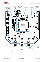
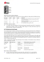
Figure 19: Boot and host interface configuration
Table 10 describes the DIP switch positions for configuring the boot mode and host interface options.
Boot mode
CON_2
CON_1
CON_0
Description
PCIE-UART
ON
OFF
OFF
WI-Fi through PCIe (J203), Bluetooth through USB-to-UART
(J205) or UART (J305)
SDIO-UART
ON
ON
ON
WI-Fi through SDIO (J204), Bluetooth through USB-to-UART
(J205) or UART (J305)
SDIO-SDIO
ON
ON
OFF
WI-Fi and Bluetooth through SDIO (J204)
Table 10: Boot mode selection options
☞
The UART interface for Bluetooth can be accessed either directly through J305, or through the
USB type-C connector J205 via a USB-to-UART bridge. For further information about the
Bluetooth UART interface, see section 4.6.
4.10
Antenna interfaces
The evaluation board includes two dual-band 2.4/5 GHz chip antennas (Pulse Electronics W3006) for
Wi-Fi and Bluetooth communication. Three standard 50
Ω
female SMA connectors are included to
connect external antennas or measurement instruments. The antenna interfaces are selected by
connecting designated u.FL connectors on the EVK with coaxial RF cables.
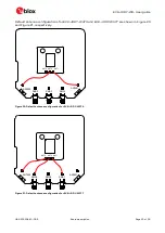
The module board has three u.FL connectors which connect to the antenna pins of the JODY-W3
series module. To use any of the chip antennas or SMA connectors on the EVK, connect a coaxial RF
cable between the u.FL connector on the module board and u.FL connector on the carrier board, as
shown in Figure 20 and Figure 21.
Table 11 describes the available radio interfaces of the modules and the default antenna interfaces
which are selected on the EVK.
Product name
Module antenna pin
Function
Default antenna interface on the EVK
EVK-JODY-
W374
ANT0
5GHz Wi-Fi and
Bluetooth
Dual-band chip antenna ANT400
ANT1
2.4/5 GHz Wi-Fi
Dual-band chip antenna ANT401
ANT2
-
-
EVK-JODY-
W377
ANT0
2.4/5 GHz Wi-Fi
SMA connector 2
ANT1
2.4/5 GHz Wi-Fi
SMA connector 1
ANT2
Bluetooth
Dual-band chip antenna ANT400
Table 11: Antenna interface configuration
☞
Connect the external antennas supplied with EVK-JODY-W377 to the selected SMA
connectors. For further information about the external antennas, see also section 1.2
SW503
CON_2
CON_1
CON_0
M_RST
OFF=1 ON=0

