


10
Chapter 2: Installation
TOUGHSwitch
™
PoE User Guide
Ubiquiti Networks, Inc.
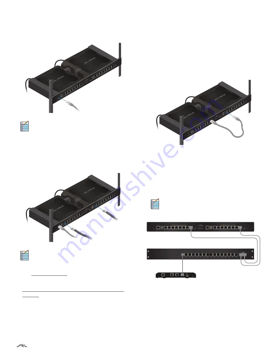
Connecting Ethernet
1. Connect an Ethernet cable from your computer or host
system to the
Management
port of TOUGHSwitch A.
Note:
By default, you can configure the
TOUGHSwitch via any port; however, we
recommend the
Management
port. (Access to
the Configuration Interface can be limited to the
Management
port only. You can configure this
setting on the
Device
tab.)
2. Connect Ethernet cables from the Ethernet ports
of your devices to the numbered ports of each
TOUGHSwitch.
Note:
PoE
is disabled by default on all numbered
ports and is not available on the
Management
port. To enable
PoE
on the appropriate ports, use
the
Ports
tab in the Configuration Interface (see
“PoE” on page 24
).
3. Uplink options are described in the following section.
After you have finished the installation, proceed to
“Configuring the TOUGHSwitch PoE CARRIER” on
page 12
.
Uplink Options
The TOUGHSwitch PoE CARRIER functions as two separate
switches. All data ports are available as uplink ports, so
you have the following two options:
Daisy-Chain Option
If you want to daisy‑chain TOUGHSwitch A and B, we
recommend that you connect an Ethernet cable from port
8 of TOUGHSwitch A to port 1 of TOUGHSwitch B. (For
clarity, the other cables are not shown in the illustration.)
Uplink to Core Switch Option
If you want to uplink TOUGHSwitch A and B to an
independent core switch, follow these instructions:
1. Connect an Ethernet cable from any numbered port of
TOUGHSwitch A to a port on the core switch.
2. Connect another Ethernet cable from any numbered
port of TOUGHSwitch B to a port on the core switch.
Note:
For clarity, the other cables connected to the
switches are not shown, except for a cable from
the EdgeRouter to the core switch.
EdgeRouter
Core Switch
TOUGHSwitch CARRIER


