


19
Chapter 2: Installation
airFiber AF-24/AF-24HD User Guide
Ubiquiti Networks, Inc.
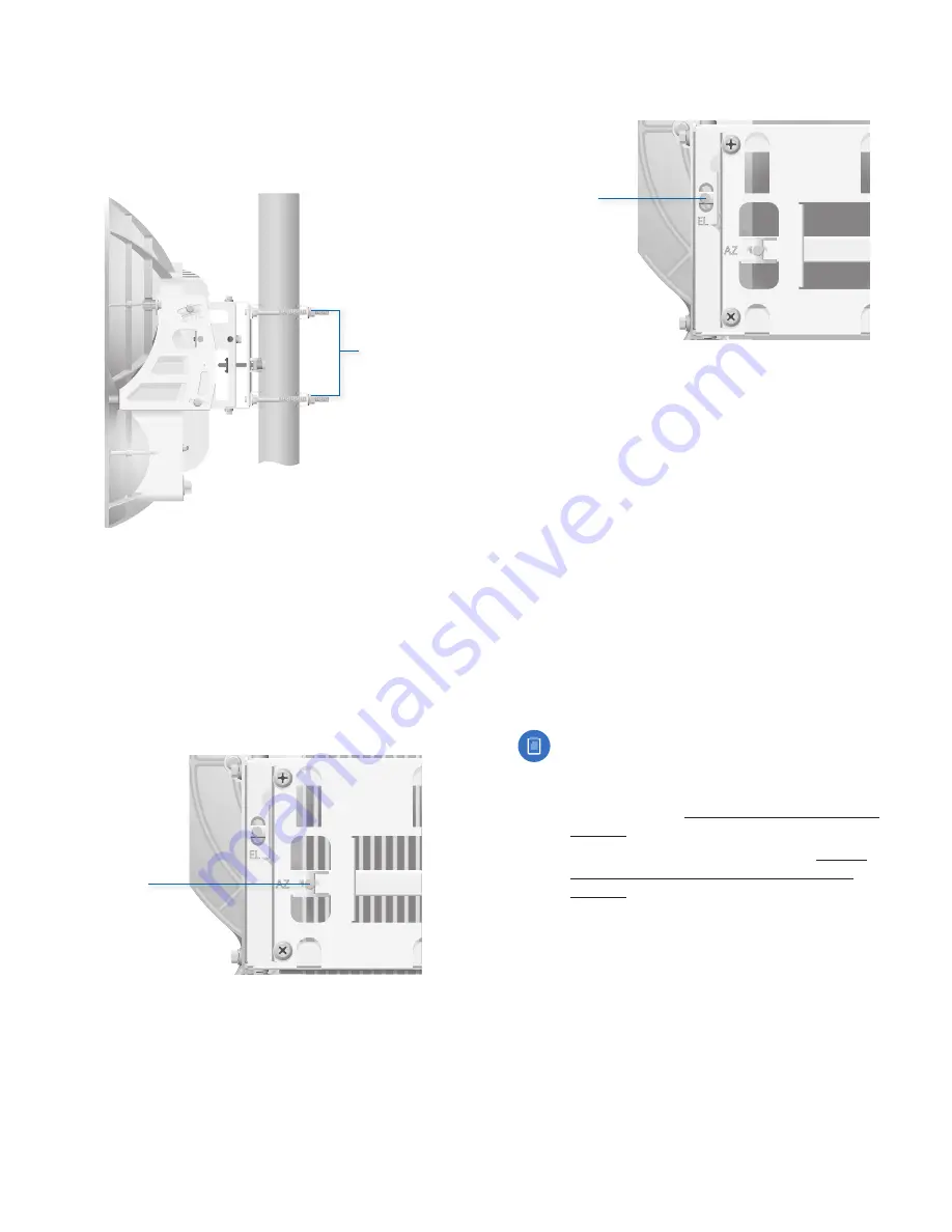
3.
Master
Aim the
Master
at the
Slave
. If necessary, adjust
the
Master
’s position on the pole:
a. Loosen the
Hex Nuts
.
b. Adjust the
Pole Mount Bracket
and
Pole Clamps
.
c. Tighten the
Hex Nuts
.
Hex Nuts
Master
4.
Slave
Listen to the audio tone of the
Slave
– the higher
the pitch, the stronger the signal strength. Aim the
Slave
at the
Master
to achieve the strongest signal
strength. If necessary, adjust the
Slave
’s position on
the pole.
5.
Master
Adjust the azimuth and elevation of the
Master
until you hear the highest pitch for the
Master
.
a. Sweep the
Azimuth (AZ) Adjustment Bolt
of the
Master
through its adjustment range.
Master
Azimuth (AZ)
Adjustment Bolt
b. Sweep the
Elevation (EL) Adjustment Bolt
of the
Master
through its adjustment range.
Master
Elevation (EL)
Adjustment Bolt
Fine-Tuning the Link
The
Azimuth (AZ)
and
Elevation (EL) Adjustment Bolts
of
the
Alignment Bracket
adjust the azimuth and elevation
within a range of ±10°. For accurate alignment, make
adjustments on one end of the link while the other
installer listens to the audio tone at the other end of the
link. Do NOT make simultaneous adjustments on the
Master
and
Slave
.
1.
Slave
Adjust the azimuth and elevation of the
Slave
until the other installer hears the highest pitch for the
Master
.
2.
Master
Adjust the azimuth and elevation of the
Master
until the other installer hears the highest pitch for the
Slave
.
3. Repeat steps 1 and 2 until you achieve a symmetric
link, with the received signal levels within 1 dB of each
other. This ensures the best possible data rate between
the airFiber radios.
Note:
If you have difficulty discerning whether the
link is symmetric, you can use one of the following
methods to determine more precise received
signal level readings.
• LED Display (See
“Using the LED Display” on
page 13
.)
• airFiber Configuration Interface (See
“Using
the airFiber Configuration Interface” on
page 15
.)
4. Lock the alignment on both airFiber radios by
tightening all eight
Lock Bolts
on the
Alignment Bracket.
Listen to the audio tone for each airFiber AF-24 to ensure
that the value remains constant while tightening the
Lock Bolts
. If the audio tones change during the locking
process, loosen the
Lock Bolts
, finalize the alignment of
each airFiber AF-24 again, and retighten the
Lock Bolts
.
Summary of Contents for airFiber 24
Page 1: ...24 GHz Point to Point Radio Models AF 24 AF 24HD ...
Page 2: ......
Page 24: ...20 Chapter 2 Installation airFiber AF 24 AF 24HD User Guide Ubiquiti Networks Inc ...
Page 28: ...24 airFiber AF 24 AF 24HD User Guide Ubiquiti Networks Inc ...
Page 32: ...28 Chapter 4 Dashboard airFiber AF 24 AF 24HD User Guide Ubiquiti Networks Inc ...
Page 36: ...32 Chapter 5 Wireless Tab airFiber AF 24 AF 24HD User Guide Ubiquiti Networks Inc ...
Page 40: ...36 airFiber AF 24 AF 24HD User Guide Ubiquiti Networks Inc ...
Page 44: ...40 Chapter 7 Services Tab airFiber AF 24 AF 24HD User Guide Ubiquiti Networks Inc ...
Page 48: ...44 Chapter 8 System Tab airFiber AF 24 AF 24HD User Guide Ubiquiti Networks Inc ...
Page 54: ...50 Chapter 9 Tools airFiber AF 24 AF 24HD User Guide Ubiquiti Networks Inc ...
Page 60: ...56 Appendix B Safety Notices airFiber AF 24 AF 24HD User Guide Ubiquiti Networks Inc ...
Page 68: ...w w w u b n t c o m ...


