


6
Chapter 2: Installation
airFiber AF-24/AF-24HD User Guide
Ubiquiti Networks, Inc.
Installation Requirements
• 17 mm (
11/16
") wrench
• 13 mm (½") socket wrench or driver
• Clear line of sight between airFiber radios
• Clear view of the sky for proper GPS operation
• Mounting location with < 0.5° displacement due to twist
and sway under wind loading
• Mounting point:
• At least 1 m (3.28 ft) below the highest point on the
structure
• For tower installations, at least 3 m (9.84 ft) below the
top of the tower
• Ground wires – min. 8 AWG (10 mm
2
) and max. length:
1 m (3.28 ft). As a safety precaution, ground the
airFiber radios to grounded masts, poles, towers, or
grounding bars.
WARNING:
Failure to properly ground your
airFiber units will void your warranty.
• (Recommended) 2 Outdoor GigE PoE surge protectors
Note:
For guidelines about grounding and
lightning protection, follow your local electrical
regulatory codes.
• Outdoor, shielded Category 5e (or above) cabling
and shielded RJ-45 connectors should be used for all
wired Ethernet connections. Category 6 is required for
installations with long cable runs (up to 100 m).
We recommend that you protect your networks
from harmful outdoor environments and destructive
ESD events with industrial-grade shielded Ethernet
cable from Ubiquiti Networks. For more details, visit
www.ubnt.com/toughcable
Installation Overview
We recommend that you configure your paired airFiber
radios before mounting. Below is an overview of the
installation with specific details on the following pages:
• Connect Power over Ethernet to the
Data
port, and
connect an Ethernet cable between your computer and
the
Config
port.
• Configure the device settings in the airFiber
Configuration Interface.
• Once configuration is complete, disconnect the cables
to move the airFiber radios.
• Reconnect at the site.
• After you have mounted the airFiber radios, establish
and optimize the RF link.
Note:
Throughout the rest of this chapter, only
the AF-24 is shown in illustrations (the AF-24HD is
similar), unless necessary to avoid confusion.
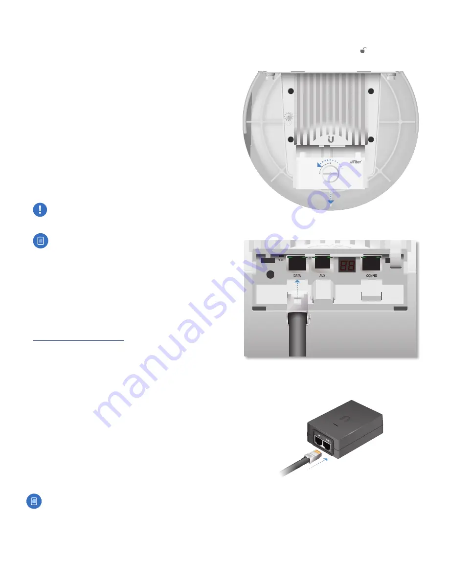
Connecting Power over Ethernet
1. Turn the
Cover Lock
to the
Unlocked
icon. Slide the
Port Cover
down to remove it.
24 GHz
2. Connect an Ethernet cable to the
Data
port.
3. Connect the other end of the Ethernet cable from the
Data
port to the Ethernet port labeled
POE
on the PoE
Adapter.
Summary of Contents for airFiber 24
Page 1: ...24 GHz Point to Point Radio Models AF 24 AF 24HD ...
Page 2: ......
Page 24: ...20 Chapter 2 Installation airFiber AF 24 AF 24HD User Guide Ubiquiti Networks Inc ...
Page 28: ...24 airFiber AF 24 AF 24HD User Guide Ubiquiti Networks Inc ...
Page 32: ...28 Chapter 4 Dashboard airFiber AF 24 AF 24HD User Guide Ubiquiti Networks Inc ...
Page 36: ...32 Chapter 5 Wireless Tab airFiber AF 24 AF 24HD User Guide Ubiquiti Networks Inc ...
Page 40: ...36 airFiber AF 24 AF 24HD User Guide Ubiquiti Networks Inc ...
Page 44: ...40 Chapter 7 Services Tab airFiber AF 24 AF 24HD User Guide Ubiquiti Networks Inc ...
Page 48: ...44 Chapter 8 System Tab airFiber AF 24 AF 24HD User Guide Ubiquiti Networks Inc ...
Page 54: ...50 Chapter 9 Tools airFiber AF 24 AF 24HD User Guide Ubiquiti Networks Inc ...
Page 60: ...56 Appendix B Safety Notices airFiber AF 24 AF 24HD User Guide Ubiquiti Networks Inc ...
Page 68: ...w w w u b n t c o m ...


