background image

7

109838-01 - 5/20

 X-PV

Installation, Operating & Service Manual

4

 Locating the Boiler

A.   Clearances:


•  Provide clearance between boiler jacket  


and combustible material in accordance with  


local fire ordinances.  Observe minimum  


clearances shown in  Figure 4.1 to avoid 


potential fire hazard.  Except as noted, these  


clearances apply to all combustible 


construction as well as noncombustible walls,  


ceilings and doors.


Front - 4”


Left Side - 4” 


Right Side - 1” 


Rear - 1”


Top (Closet installation) - 18” 


Top (Alcove installation) - 4"


Note:  As  an  alternate  to  the  side  clearances                                                                                                

shown above, the following minimum side 

clearances may be used:


Left Side – 1”


Right Side – 4”

  WARNING

      Failure to observe the following location 

requirements could result in a fire, explosion or 

carbon monoxide (CO) hazard.

!


Note that if this option is exercised, the relief valve 

and gauge must still be installed in the location 

shown in Figure 4.1. The drain valve on the left 

side of the boiler must also remain accessible.


•  Provide practical service clearances. A  24”  


service clearance from the jacket is   


recommended on the left, right, and front  

       of the boiler.  These clearances may be 


       reduced to those shown in Figure 4.1,    


however servicing the boiler will become  

       increasingly difficult as these service clear- 

       ances are reduced.  

B.   Provide a minimum clearance of 1/2" from hot  

      water pipes to combustible material.

C.   Do not install this boiler in a location where 


gasoline or other flammable vapors or liquids,  


or sources of hydrocarbons (i.e. bleaches, 


cleaners, chemicals, sprays, paint removers, 


fabric softeners, etc.) are used or stored.

D. Do not install this boiler in an area where large  

  amounts of airborne dust will be present, such   

     as a workshop.

E.  The boiler must be installed on a hard level             

     surface. This surface may be combustible.

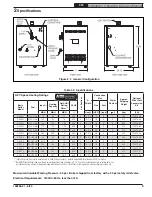
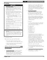
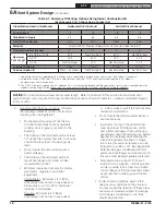
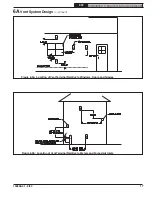
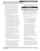
Figure 4.1:  Minimum Clearances To Combustible Construction

Summary of Contents for X-PV Series

Page 1: ...ustment alteration service or maintenance can cause property damage injury or loss of life For assistance or additional information consult a qualified installer service agency or the gas supplier Rea...

Page 2: ...which if not avoided may result in moderate or minor injury or property damage DANGER Explosion Hazard DO NOT store or use gasoline or other flammable vapors or liquids in the vicinity of this or any...

Page 3: ...tilation air supply to the boiler Burn Hazard This boiler contains very hot water under high pressure Do not unscrew any pipe fittings nor attempt to disconnect any components of this boiler without p...

Page 4: ...le This boiler is vented using an approved vertical or horizontal AL29 4C stainless steel venting system which is not included with the boiler This boiler requires an adequate source of clean combusti...

Page 5: ...gal lbs PN X PV3N NAT GAS 70 60 52 85 0 3 12 3 4 1 2 3 2 260 110019 03 X PV4N NAT GAS 105 90 78 85 0 4 15 1 2 1 2 3 3 310 110019 04 X PV5N NAT GAS 140 120 104 85 0 5 18 1 2 1 2 3 4 360 110019 05 X PV...

Page 6: ...nting to confirm that the maximum intake pipe length will not be exceeded and that the intake terminal may be located as required on the outside of the building E Make sure that the boiler is correctl...

Page 7: ...ve and gauge must still be installed in the location shown in Figure 4 1 The drain valve on the left side of the boiler must also remain accessible Provide practical service clearances A 24 service cl...

Page 8: ...od cannot be used in all cases see discussion below Direct Venting Combustion air is pulled directly from outside using the appropriate Direct Vent Conversion Kit shown in Table 2 2 with installer sup...

Page 9: ...The minimum opening dimension is 3 inches Minimum opening free area is 100 square inches per opening If the total volume of both the boiler room and the room to which the openings connect is less tha...

Page 10: ...room and basement will be 350ft3 6400ft3 6750ft3 and 6750 135 50ft3 per 1000 BTU hr In the absence of one of the conditions described in 6 above this arrangement should provide an adequate fresh air s...

Page 11: ...te They are also designed to provide a gas tight seal at all joints and seams so that flue gas does not enter the building Each approved vent system has unique method for installation do not attempt t...

Page 12: ...l location also see Figure 6 9 Terminal must be at least 4 feet below or 4 feet horizontally from any operable window door or gravity air inlet into the building The bottom of the terminal must be at...

Page 13: ...PV Installation Operating Service Manual Figure 6 2 Horizontal Direct Exhaust Vent System Vent Options 1 2 Figure 6 3 Tee Terminal Figure 6 4 Optional Miter Terminal X PV3 thru X PV6 Only 6AVent Syst...

Page 14: ...for these caps are shown in Table 6 7 7 Vertical Vent Terminal Locations Vent Options 3 4 The lowest discharge opening on the cap must be at least 2 feet above any object located within 10 feet Figur...

Page 15: ...15 109838 01 5 20 X PV Installation Operating Service Manual Figure 6 6 Vertical Direct Exhaust System Vent Options 3 4 6AVent System Design continued...

Page 16: ...CGSWTTM 4 CGSWC 4 NOTES 1 See vent system manufacturer s literature for other part numbers that are required such as straight pipe elbows firestops and vent supports 2 All Heat Fab condensate traps sh...

Page 17: ...Installation Operating Service Manual Figure 6 9a Location of Vent Terminal Relative to Windows Doors and Grades 6AVent System Design continued Figure 6 9b Location of Vent Terminal Relative to Meters...

Page 18: ...ng Service Manual Figure 6 9c Location of Vent Terminal Under Overhangs Y X Max Overhang 0 12 NOT PERMITTED 12 48 17 29 X minus 7 Greater than 48 17 29 36 Note Overhang may not be ventilated if Y is l...

Page 19: ...lowing steps shall be followed with each appliance remaining connected to the common venting system placed in operation while the other appliances remaining connected to the common venting system are...

Page 20: ...prior to assembly Figure 6 10 Installation of Vent Adapter C Vent System Assembly 1 General Assembly Notes a Where the use of silicone is called for in the following instructions use GE RTV 106 for th...

Page 21: ...g Replace and tighten the clamp on the vent adapter Figure 6 11 Connection of First Vent Pipe to Boiler Vent Adapter 4 Complete the rest of the vent system in accordance with the vent manufacturer s i...

Page 22: ...ided with the boiler The relief valve shipped with the boiler is set to open at 30 psi This valve may be replaced with one having a pressure up to the Maximum Allowable Working Pressure shown on the r...

Page 23: ...set LWCO to either break120VAC power to the boiler or break the external limit connection shown in Section 9 Figure 7 2 Standard Boiler Piping 7 Manual Reset High Limit Required by some codes This con...

Page 24: ...iler water flow through the indirect water heater called for by the indirect water heater manufacturer 2 Large Water Volume and Low Temperature Systems Use a system bypass if boiler is to be operated...

Page 25: ...conjunction with a chiller pipe the boiler and chiller in parallel Use isolation valves to prevent chilled water from entering the boiler 5 Air Handlers Where the boiler is connected to air handlers t...

Page 26: ...als in accordance with local plumbing codes and requirements of gas supplier In absence of such requirements follow National Fuel Gas Code ANSI Z223 1 NFPA 54 b Use thread compounds pipe dope resistan...

Page 27: ...properly regulate gas pressure at the input of the smallest appliance If the regulator can not do this two or more additional regulators are required Consult regulator manufacturer and or local gas su...

Page 28: ...e boiler All 120VAC connections to the boiler itself are made inside the junction box in the boiler vestibule 120VAC connections are Ground 120VAC Hot Black 120VAC Neutral White System Circulator Hot...

Page 29: ...e thermostat circuits If such a power source is present it could destroy the boiler s control One example of an external power source that could be inadvertently connected to the low voltage connectio...

Page 30: ...Auxiliary Limit Jumper remove per optional kit instructions YE BL BL RD WH IDL 1200 LWCO RD WH BL RD Notes 1 If any of the original wire supplied with the appliance must be replaced it must be replace...

Page 31: ...al By Installer Wire Nut Plug Connection Screw Terminal 120 VAC Internal Control Wiring 120 VAC Wiring Low Voltage Internal Control Wiring Low Voltage Wiring Ladder Diagram Legend Flame Rollout Switch...

Page 32: ...ns shown in Figure 10 3 Upon initial start up the gas train will be filled with air Even if the gas line has been completely purged of air it may take several tries for ignition before a flame is esta...

Page 33: ...33 109838 01 5 20 X PV Installation Operating Service Manual Figure 10 3 Operating Instructions 10 Start up and Checkout continued...

Page 34: ...t Burner Flame Natural Gas Only Pilot produces single flame Flame should be steady medium hard blue enveloping 3 8 to 1 2 inch of igniter sensor tip See Figure 10 6 LPGasOnly Thepilotburnerproducesthr...

Page 35: ...d for at least 30 minutes check the boiler and heating system piping for leaks Repair any leaks found at once U Inspect the vent system for flue gas leaks Repair any leaks found before leaving the boi...

Page 36: ...This is the default mode of operation for the control In it the display alternates between StA and a number indicating the current status of the boiler A list and description of these status numbers i...

Page 37: ...Signal uA ERROR MODE Visible when Lockout is Present Code for Error Present Table 13 0 total burner Cycles Total Run Time hrs Press I Return to Status Mode Press or Boiler in Lockout Temperature Unit...

Page 38: ...n Status 2 for 60 seconds and air pressure switch remained closed Boiler will remain in this state until the air pressure switch opens 12 Pressure Switch failed to close Control waited in Status 3 for...

Page 39: ...stic hot water DHW Note that if the dh zone on the S9361A is used as a second heating zone see Table 12 6 this parameter will be shown as OFF and tt will be shown as ON when this zone calls for heat F...

Page 40: ...n should be exercised before setting this value to something other than zero Before doing so verify that the system will permit flow e g flow is not completely cut off by closed zone valves and that t...

Page 41: ...peration Example Call for Heat From Use of DHW Zone Thermal Purge Settings Boiler Temp at Begin Call Boiler Behavior Time Pt Start Temp St 1 T T N A 2 min 140F 130 Heating Circulator starts immediatel...

Page 42: ...dh dh ON OFF ON ON ON DHW dh dh ON OFF ON ON ON DHW dh dh OFF ON ON ON OFF DHW dh dh OFF ON OFF OFF ON DHW dh dh OFF OFF ON ON OFF Heat dh tt2 ON or OFF ON OFF OFF ON Heat dh tt2 ON or OFF OFF ON ON...

Page 43: ...problem with the fan If this switch must be replaced it must be replaced with an identical switch or one that is shown in this documentation as being a suitable replacement for this boiler see Parts S...

Page 44: ...re listed on the NIOSH website 2 Long sleeved loose fitting clothing that is sufficiently tight around potential entry points for RCF dust 3 Gloves 4 Eye protection such as goggles safety glasses with...

Page 45: ...he boiler 2 Inspect the flue passages for signs of blockage If there is any carbon in the combustion chamber or the flue passages clean the heat exchanger before proceeding further See the cleaning pr...

Page 46: ...els 5 Unplug the fan 6 Disconnect the pressure switch hoses from the pressure switch being careful to note their orientation 7 Remove the four 10 sheet metal screws holding the canopy onto the block A...

Page 47: ...this screw has deteriorated replace it C Service Notes 1 Pressure Switch This boiler is equipped with a differential pressure switch which makes when there is adequate flue gas flow through the boile...

Page 48: ...48 109838 01 5 20 X PV Installation Operating Service Manual Figure 12 3a Pressure Switch Connections Figure 12 3b Measuring Pressure Across Pressure Switch 12 Service and Maintenance continued...

Page 49: ...tive control or component is generally the least likely cause Before replacing a component try to rule out all other possible causes 5 When checking voltage across wiring harness pins be careful not t...

Page 50: ...ensor Defective control 35 Duplicate Zone Error code reserved for future use 57 Grounded pilot electrode Condensate or foreign material is shorting pilot electrode to ground Ignition cable insulation...

Page 51: ...electrode or Ground strap damaged replace pilot If you cannot hear spark at all replace control StA 6 Spark but no pilot flame Low inlet gas pressure Plugged kinked or leaking pilot tubing Plugged pil...

Page 52: ...ure switches shown are for sea level configured boilers For boilers installed at elevations above 2000 ft consult the local U S Boiler Company representative or the factory for the correct main burner...

Page 53: ...t 2K Manifold Support Bracket 2L Burner Access Panel 2M Flame Rollout Switch 3D Main Burner with Pilot Bracket 3F Main Burners less Pilot Bracket 2J Base Gasket Kit 6206002 1 2L Burner Access Panel 11...

Page 54: ...Orifice Natural Gas Sea Level 2000ft 110408 01 1 56 Gas Orifice LP Gas Sea Level 2000ft 110409 01 1 49 Gas Orifice Natural Gas 2001 10 200ft 110618 01 1 57 Gas Orifice LP Gas 2001 10 200ft 110619 01 1...

Page 55: ...L INFORMATION AND ITS CONTENTS ARE THE SOLE PROPERTY OF CROWN BOILER COMPANY INC ANY REPRODUCTION IN PART OR THIRD ANGLE REVISIONS REV EN DATE DESCRIPTION DWN CHK A 3 4 2020 INITIAL RELEASE JP JP GY 4...

Page 56: ...Service Manual Key No Description Part Number Quantity 3 Section 4 Section 5 Section 6 Section 7 Section 8 Section 5A Burner Cover Natural Gas Only 110402 03 1 110402 04 1 110402 05 1 110402 06 1 1104...

Page 57: ...ction 7 Section 8 Section 6A Integrated Boiler Control 103968 02 1 6B Transformer 106034 01 1 6C Hydrolevel IDL 1200 LWCO Kit 106495 02 1 6D 4C 4D Air Pressure Switch w Tubing Sea Level to 2000ft 1104...

Page 58: ...4 Section 5 Section 6 Section 7 Section 8 Section 7A Left Jacket Panel 110418 01 1 7B Right Jacket Panel 7C Rear Jacket Panel 110419 03 1 110419 04 1 110419 05 1 110419 06 1 110419 07 1 110419 08 1 7D...

Page 59: ...t Number Quantity 3 Section 4 Section 5 Section 6 Section 7 Section 8 Section 8A Water Manifold 109614 01 1 8B Temperature Pressure Gauge 105894 01 1 8C 3 4 Safety Relief Valve 30 psi 109038 01 1 8D B...

Page 60: ...tion Operating Service Manual Key No Description Part Number Quantity 3 Section 4 Section 5 Section 6 Section 7 Section 8 Section 9A Line Voltage Wire Harness 110423 01 1 9B Low Voltage Wire Harness 9...

Page 61: ...owing galvanized components 2 ft vertical pipe 1 90 elbow 5 ft horizontal pipe 1 90 elbow 3 ft horizontal pipe 1 termination fitting The Vent Option 5 column in Table A 2 describes a horizontal direct...

Page 62: ...Not Permitted Not Permitted 40 ft Not Permitted Not Permitted 40 ft Maximum Intake Length X PV3 4 60 ft Not Permitted Not Permitted 60 ft Not Permitted Not Permitted X PV5 6 Not Permitted 50 ft Not Pe...

Page 63: ...cted on the roof 6 Terminal Offsets When horizontal terminals are offset as shown in Figure A 5 both must be offset vertically by the same distance 7 Support of Intake Piping Support intake piping eve...

Page 64: ...64 109838 01 5 20 X PV Installation Operating Service Manual Figure A 5 Horizontal Terminal Offsets Figure A 6 Vertical Direct Vent System Vent Options 8 10 Appendix A continued...

Page 65: ...ake system components 2 If metallic smoke pipe is used use at least three sheet metal screws per joint Seal the outside of all joints 3 The male end of metallic smoke pipe will fit inside the air inle...

Page 66: ...configurations Boilers that are factory configured for use at altitudes above 2000ft are marked as such on both the packaging and rating plate The high altitude orifice and pressure switch are factor...

Page 67: ...t which the boiler is to be installed See Table B 1 for the correct configuration Failure to properly configure this boiler for the installation altitude could cause personal injury or death due to ca...

Page 68: ...condensing during these heating season shoulders is unlikely to cause problems Larger volume systems during the shoulder heating seasons or systems with aggressive set back or low temperature systems...

Page 69: ...mperature sensor measures boiler inlet temperatures This temperature signal is sent to a variable speed pump that will ensure boiler inlet temperatures are always greater than the factory by pass kit...

Page 70: ...st be used and if applicable a product approved air intake must be used Installation shall be in strict compliance with the manufacturer s instructions A copy of the installation instructions shall re...

Page 71: ...71 109838 01 5 20 X PV Installation Operating Service Manual SERVICE RECORD DATE SERVICE PERFORMED...

Page 72: ...72 109838 01 5 20 X PV Installation Operating Service Manual U S Boiler Company Inc P O Box 3020 Lancaster PA 17604 1 888 432 8887 www usboiler net Notes...

Reviews: